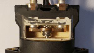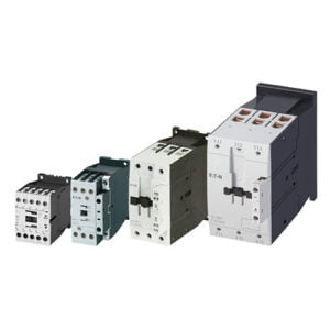
Contactors are more than just a large relay, their internal construction is designed to be capable of carrying far higher currents and “making and breaking” on large loads.
Rather than moving the common contact back and forth on a pivoting armature, contactors move a large bar towards or away from the contacts, around this bar are normally arc-suppression devices to limit the effects of an arc from being pulled.
Because the bar is moved away from both terminals at once, there are two air gaps between the terminals meaning there is better isolation.
Contactors are commonly used on large DC loads such as Solar Panels, or wind turbines due to this arc suppression, and double isolation. Battery Electric Vehicles (such as the Nissan Leaf, Jaguar iPace, and Tesla cars) make use of contactors in their battery pack to de-energise the battery from the High Voltage Junction Box.
Some contractors have an additional physical switch actuated by the movement of the bar to confirm that the terminals have not welded shut. This safety feature can be used to send a signal back to the controller.
While most contractors are actuated by an electromagnet similar to that of a relay, pneumatically actuated contractors are available to give even higher degrees of isolation between the current being switched and the control circuitry.
Contactor terminal arrangements
Contactors are also available in multiple pole versions (see the photo of Eaton’s three-phase contactors above), however, for simplicity, I am just going to cover single pole variants. but multi-pole variants are available, where magnetising the coil actuates multiple bars at once.
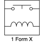
1 Form X Contactors
Similar in operation to a “1 form A” relay, “1 Form X” contactors are normally open. the application of current to the coil will magnetise the coil, pulling the bar into contact with the terminals and allowing current to flow between the input and output.
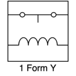
1 Form Y Contactors
Similar in operation to a “1 form B” relay, “1 Form Y” contactors are normally closed. the application of current to the coil will magnetise the coil, pulling the bar out of contact with the terminals and preventing current to flow between the input and output.
