I can’t remember where I came across the REEcorner™ module concept. (I think it was probably LinkedIn) The REEcorner looks like it could be adapted to work nicely on my DefLander ‘Tot Rod’/’ToyLander’, I have chosen the name “ToyCorner” as hopefully, it is far enough away from REE’s trademark for me not to get any letters from their lawyers.
The REEcorner™ integrates all critical vehicle components (steering, braking, suspension, powertrain, and control) into a single compact module between the chassis and the wheel. Each REECorner™ is completely independent and controlled by its own electronic control unit (ECU), with a REEcenter ECU that controls all corner-level functions.
The functionality of intrest brought out to the REEcorner, is the Drive-by-wire, Steer-by-wire and Brake-by-wire parts of the “Smart corners”
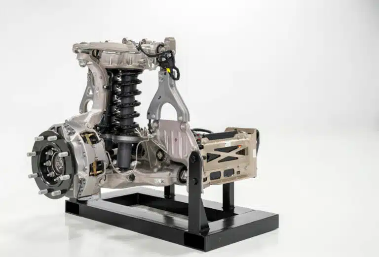
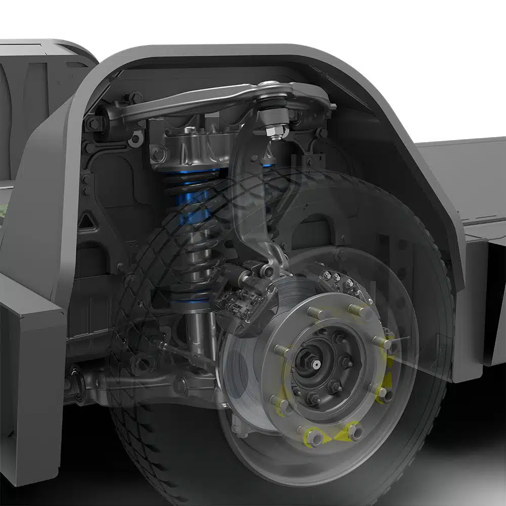
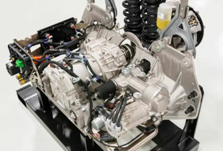
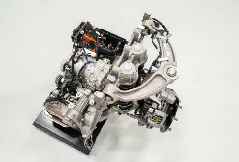
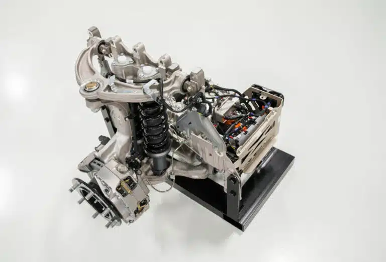
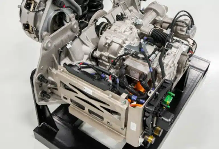
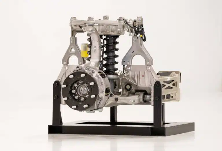
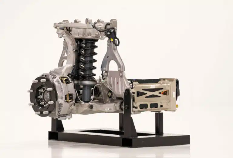
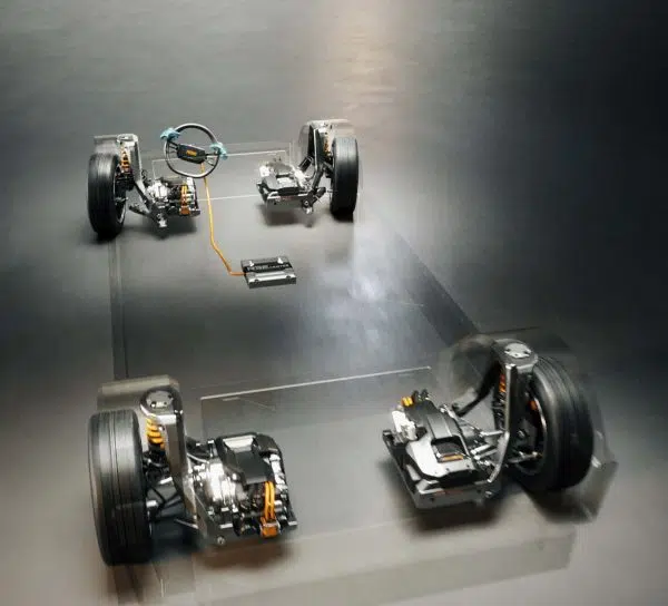
ToyCorner TotRod Drive system
For the DefLander version of this, I am going to design each “smart corner” to contain suspension, brakes, drive, and steering. This should simplify the architecture of my DefLander since each corner will only need a power connection and a data connection.
Data will be a bi-directional CAN bus, and power will be a single 48 Volt DC supply. Logic voltage levels and other required power levels can be generated on the module.
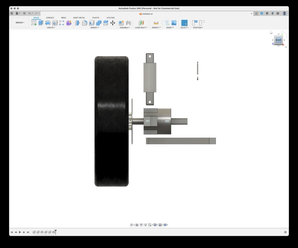
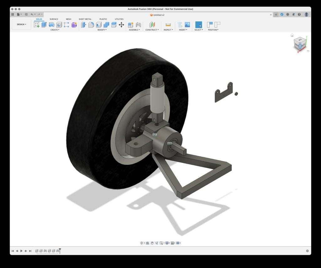
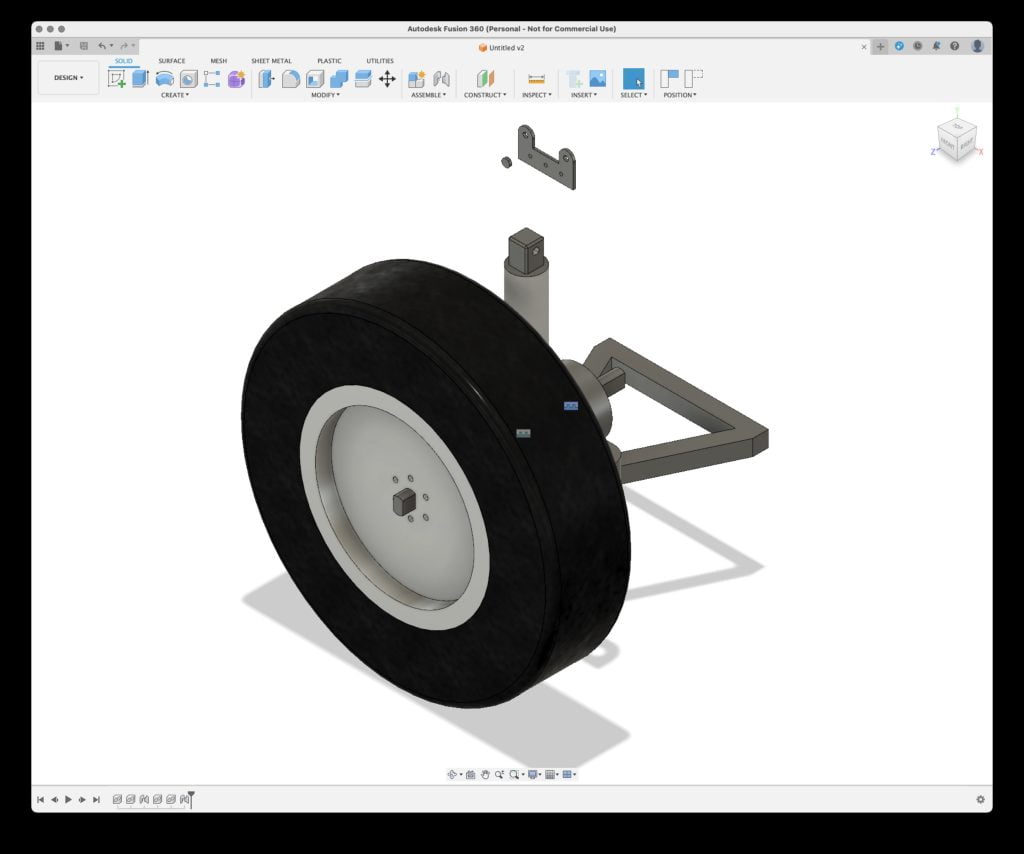
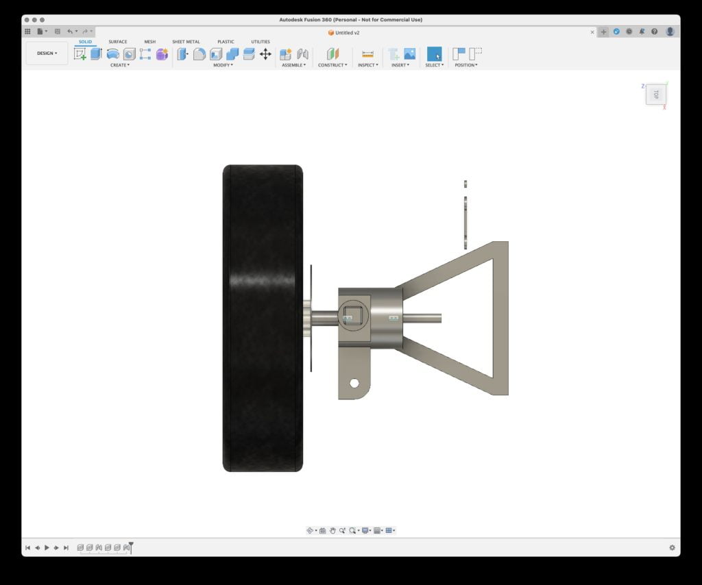
As you can see from these quick renders in Fusion 360, my plan is to have a MacPherson strut style arrangement, with the suspension component from the rear of a mountain bike as the coil spring, shock absorber and damper assembly. The disk brake is also taken from a mountain bike with the actuation being performed by a RC servo, which will all be mounted on the steering knuckle/hub carrier. The traction motor will be mounted on the opposite side to the steering gear tie/track rod, with the reduction gear set being mounted inboard of the hub carrier.
Chances are that I will mount the steering RC servo on the hub carrier as well, this allows the steering gear tie/track rod to be securely mounted on the vehicle chassis, probably at the same mounting point as the lower control arm, reducing the number of attachment points required.
I will need to do some analysis of forces, and work out what reduction ratio is required for the drive motor.


34 thoughts on “ToyCorner Idea”
Nice, you will appreciate the suspension! Take a look at the steering section of the wiki. There’s some photos of how I implemented it with hoverboard motors for more inspiration.
CYBR TRK v1 used a windscreen wiper motor, H bridge controller, and a feedback potentiometer for fly by wire steering. James Bruton did a video about DIY wiper servos which explains it well. It had plenty of torque and was responsive enough to be unnoticable, but as Keegan pointed out, not quite allowed in the hacky rules.
I was trying to avoid a physical connection between the steering wheel and the steering arm of the ToyCorner.
The idea was to allow full four-wheel steering, braking, and drive. and allow for quick removal of each drive system for maintenance and upgrade.
Hey this is a great idea for sure I would likely look more into kinematics of linkage as mountain bike shocks in the forum are tuned from factory for 65-90kg damper wise and are designed ro work with a average leverage ratio of about 2.5-3.0:1
Everything else looks amazing in thw forum its for a rc car but what are you trying to build thus system into?
On the comments thread there is a discussion with Phil Hardwick on this very topic, he has suggested that there are aftermarket springs available that have a lower compression force
How about a simple wheel integrated motor with regen switching and infinitely variable tractive force.
Mark J. Carter there is a requirement in the Hacky Racers rules for physical brakes.
I have got a redesign in these comments using balance board motors.
The hub is getting smaller… this is a design based on balance board wheel hubs, and uses M6 Rod end bearings on the lower control arm to allow for motion in all required axis.
The suspension coil will not be verticle but will be angled to help with the scrub radius.
for the steering servo, if you’re looking for a low effort, off the shelf solution, I’ve found ASMC‑04A to work quite well. One of them didn’t quite have enough torque for me to steer both (undriven/unbraked) front wheels on Rule Zero, but then thats wide wheels, huge scrub radius and some kingpin inclination. One per wheel with better geometry, they could work fine. There are several variants with different cost/speed/torque profiles. (ASMC/ASME 03A/03B/04A/04B etc)
I used a ~100kgcm model. I doubt the 40kgcm rc servos will be strong enough. Rough numbers: 25kg vertical load on a wheel and braking hard enough on tarmac to lock up that wheel means a friction force of ~20kg. with a scrub radius of 10cm, thats 200kgcm. way out of the range of rc servos. Maybe my made up numbers are conservative, but I think you’ll have to make significant compromises to get it within the range of RC servos.
I saw another reply on your website (how did you get the comments to mirror from Facebook to there?) about the scrub radius and reducing the size of the knuckle. Are you going for a vertical steering pivot, or will you have some inclination so you can minimise scrub radius whilst having a substantial steering knuckle?
Manual copy/pasta… its a pain, but it allows me to keep track of comments and suggestions in one place.
I was thinking about The steering axis inclination, to reduce the scrub radius, but also I am looking to reduce the size of the steering knuckle. both of which will reduce the size requirements for the ToyCorner.
I am looking for traction motor recommendations,
I am looking at building a four-wheel drive TotRod which doubles as a Hacky Racer.
Each corner will have its own Motor, Steering Servo, and Brake disk (Brake-by-wire) mounted on the hub carrier.
I am going to be re-watching Matt Denton’s videos to see his 3D printer settings. – https://www.youtube.com/channel/UCbOrJwJsd4vFS4aLIILa_7Q
Just as an FYI too, if you’re going to be racing then brakes and steering have to be mechanical. I love seeing stuff like this but as it’s safety critical it’s one that we can’t bend on. Regen braking can be used, but you have to have mechanical brakes as your primary source of stopping power.
Going to be following with interest though, I’ve been designing something similar for The Luggage. It sorely needs suspension and steering on the corner wheels would help greatly with heavier loads. I count myself in that 🤣
“The Luggage”? as in from Discworld?
The callipers for the brakes will physically actuate onto brake disks. any regenerative braking will be a function of removing power demand from the acceleration, any brake demand on the brake pedal will remove all power demand, and apply friction brakes.
The steering and braking systems will still be mechanical.
Yup, it’s been a long running joke since EMF 2016. I have a cargo robot that works and have plans to add whegs with multiple feet on it at some point along with a wooden chest outfit for it
note “mechanical brakes” means a mechancial connnection from the driver to the brake, either hydraulic, cable or otherwise, not an electrical signal where powerloss (e.g. because the fuse, required for racing, has blown) could stop the brakes from working. Even if the power supply for your braking is separate from traction power, we want there to be a purely mechanically actuated brake on at least two wheels. . note you could have electronic signals driven brakes on either the front or rear wheels, and mechanical for the other two.
We’re not stipulating this to be awkward, we’ve had these systems fail before and there’s been some potentially dangerous near misses that we want to avoid happening again.
I can also run a physical Bowden cable without any issues.
apologies if my comments are coming across as negative, I think it’s a cool concept and I wish you luck with your build, whether you end up racing or not.
Even if I don’t race, I am planning on having the system fail-safe!
Depending on performance goal amd size, this style design lends itself to hoverboard motors as they are a hub motor design, you’d therefore need no active transmission parts like belts, chains, driveshafts etc. Relatively cheap and easy to source from broken hoverboards, though may not give fantastic speed.
I have four of them lying around somewhere, the issue with them is going to be mounting the disk brakes to them?
I think someone has managed to? Mark Mellors maybe?
I found this image in the HackyRacers Facebook group (https://www.facebook.com/groups/770080473171308/), I will keep looking to see if there are other images or details.
https://www.facebook.com/groups/770080473171308/posts/1870198536492824/
https://hackyracers.co.uk/wiki/index.php/Brakes
Thank you for the links 🙂
This is very cool! 🛞🤔
An interesting concept, MacPherson strut is quite tricky to set up though. if you’re looking at mtb rear shocks, watch out for the spring rates as they are REALLY stiff. I started with ones for a kids MTB and then had to find softer springs. With Macpherson strut you need really quite soft springs as you get no mechanical leverage from the swing arm.
your knuckle arm CAD looks like there’s quite a scrub radius between wheel and pivot point. this might make it a bit jerky to drive on rougher ground if going at any speed. here’s an exploded view of the hubs I made for my daughters defender. green bit is a trailer wheel hub machined to remove the bearings. Blue are thin section ball bearings. yellow is a machined piece to join the wheel hub to the drive shaft using a taper lock and pin drive. Lots of work in this though…
I’m not sure what the budget for hacky racers is, I’ve looked at it a couple of times, but never really had the time to pursue it, what I would say is keep the chassis simple. My daughters defender is massively over complicated, heavy and expensive. my boys car is an upgraded piece of cheap plastic tat from something like Smyth’s toy store. 2wd with bouncy tires and small brushless motors and goes just as well over the rough stuff!
Thanks for pointing out the scrub radius, I have been looking at that, and wondering if it would be an issue, I think to reduce that I am going to move the braking components inboard, onto the rear of the driven gear. this will allow the wheel to move closer to the knuckle.
Thank you for the information about the MTB spring rate issue, I will have to think about how to do the springs.
I am also thinking about how to re-design the knuckle so its physically smaller.
I’m sure you already have but it’s worth researching how the macpherson strut operates. Key points are you need a rigid coupling between spring and hub so that it forms a solid unit. and that the top of the spring unit needs to be able to rotate. typical spring assemblies have a bolt-through at each end which might make it difficult to mount rigidly or allow mounting of the top to rotate. the image attached of an old vw bug front suspension gives quite a good idea of different mounting styles and shows how the springs could be mounted to the hubs in different ways. Granted this doesn’t have a drive shaft through it, but might give you some ideas.
For my sins, I worked at JLR for a while, so have seen MacPherson struts in real life, but thank you for the reminder of the physically connected aspect of the strut.
Some photos of the springs I used. the back ones are 450lbs/inch fronts ended up much softer due to different leverage.
side by side comparison of the softer front springs.
You wouldn’t happen to have a link to your spring supplier?
I’m afraid not, Pretty sure the Children’s MTB springs were an ebay thing.
https://www.ebay.co.uk/itm/385521664141?hash=item59c2e1c08d:g:vVcAAOSwdyRkKnQY&amdata=enc%3AAQAIAAAA4K51OKGPZ%2FPL9n3DuKGSqhCC5qqMiwZTpxSQhpsFkeQ3S%2F5CuTCk672yYynOw66qUWkUSRkuVJAizswk6oy3JEgoLHzAGLyXY23xo%2BLWsK1thUbsYGv9XhC5%2B7JpvB7WSqT%2BzwITzH2Lx%2FagqrELuzkyKA3LMcqMPQ94LPYInPNbGwcxx4tz5pkgr6PP8OlFjIxKvpO6YwLMpk393qgPJTnCzUbhFI%2BoWOF7awFJq8Ww1BYeXxd5NeuhiGwnvcrGmnPPg97W5Tf%2FDVSDOuH62ZVkrKpbQfjLHWEg1TauJ0uO%7Ctkp%3ABk9SR_qhr9GYYw
I don’t appear to have recorded where I got the lower rated springs, though I have a suspicion it was aliexpress as that’s where I get a lot of odd things from.