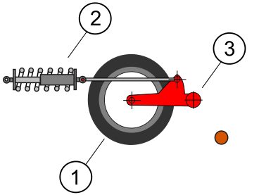
1. Roadwheel
2. Spring
3. Arm
Alexpl, CC BY-SA 4.0, via Wikimedia Commons
Due to PiWars course for “Lava Palava – Escape the volcanic eruption!” containing at least one speed-hump, and the obstacles in “The Temple of Doom – Go on an adventure and tackle the obstacles in your way!” are unlikely to be flat, there should be some compliance in the drive and suspension system to allow the robot to keep the tank tracks in contact with the floor as much as possible.
The East-Devon PiRates have an image with the dimensions for the speed hump on their page. It’s a minor segment of a circle, with a base dimension shown to be 570 mm and a height of 53 mm (The diameter of the circle is not shown).
With the maximum length of the robot being limited to 300 mm, this means that the speed hump is longer than the robot. As such the robot needs to climb one side and descend the other (rather than ride over it like the orange circle in the animation of the Polish 10TP tank’s suspension). The compliance is therefore required to keep the tracks in contact while transferring from the floor to the ramp, and the ramp to the floor, and allowing the tracks to conform to the curvature of the ramp.
I have moved away from using the Vex Robotics Tank Track and am now referencing the track design on the Speed Tank by Janka, this allows for more of the design to be 3D printed and is easier to replace anything that may get damaged in use, or perform redesigns as required. This also allows for the drive sprockets to be sized appropriately, and match the dimensions of the hull.
Suspension System Design
The suspension system we are using is a Christie-Derived system, that, unlike the suspension system in a car, uses either coil-over (dampers) in a vertical arrangement, MacPherson struts or in the case of more commercial vehicles leaf springs. Is based around a design used on full-size tanks, designed by the American engineer J. Walter Christie. The advantage of the Christie design is that it allows considerably longer movement than conventional leaf spring systems then in common use.

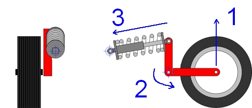
To allow for a lower profile hull base, we are using a bell crank similar to the second animation to allow for greater travel without the height required for the spring system.
Since we are using a spring under tension, rather than compression, I will be looking at using elastic bands rather than coil springs. Elastic bands allow for easy adjustments, and replacement if they get damaged.


67 thoughts on “PiWars Suspension System”
Non va bene deve stare verticale
Sorry, I don’t know Italian, but my best guess is “It’s not good, it has to be vertical”
The suspension travel doesn’t need to be verticle. I haven’t done much analysis of the advantages. but my intuition is that vertical travel means you don’t change the steering geometry as much as having the wheelbase lengthen as the road wheel travels along its arc.
However, in this case, I am not too worried about changes to steering geometry as I am neither travelling at sufficient speed or utalising Ackerman steering.
The rear suspension on my daughters tot-rod is also a similar pull rod style setup, but with a cantilever setup to use a standard compression spring.
That looks like a toylander?
It was the toylanders that gave me the idea for it, but it’s a bit bigger and a lot more complex. full time 4×4, 3 ball differentials, fully independent suspension, steel ladder chassis with lightweight plywood shell.
Somewhere on my massive project todo list is a very similar vehicle.
I have had a look at some of your other YouTube videos! and have to admit to being very impressed 🙂 I would love to know if you have a build log, or a blog anywhere I can read. I would very much like to see more photos of your tot-rod.
https://www.youtube.com/@philhardwick3601
If you search my name in https://www.facebook.com/groups/498664253631187/?ref=share there’s a build log of sorts.
Formula racing cars use springs and dampers like that, but using a parallelogram so the wheel can be mounted at 90 degrees to the suspension direction
Other people have also suggested looking at F1 cars, or the suspension from vehicles like the 2CV.
At the moment I am considering moving towards a compliment mechanism, that is a single-piece with the swing arm, allowing for simplification, of both the suspension and hull design.
If I move away from needing the swing arm to rotate around a point on the hull. I could move towards a square attachment point, that also doubles as the anchor for the ‘spring’
Your suspension will have an issue with compliance with a depression by running out of travel on the push\ pull rod. I would investigate f1 car suspension since they have a need for light weight with high strength in a small package.
The images in the post were indicative only, there is a lot of discussion about future changes in the comments section on the post – https://philipmcgaw.com/piwars-suspension-system/#comment
I have been pointed at Complient mechanisums as an option, with the abilty to adjust the spring rate, preloading and travel all in a single part.
Thinking about it further, If I desing the swing arm, and complient mechanisum in one part, I may not even need to have a rotating axis between the suspension arm and the hull.
For what it’s worth, a torsion bar system is even smaller/lighter/simpler to fix.
I am looking at a compliant mechanism, I don’t really have the internal space for a torsion bar system, as immediately behind the hull wall is the drive motor, so I have not got clear space across the entire width of the hull for the beams.
Ah fair enough. Worth noting you can make very short torsion bars, especially at this scale, but what you are describing may not be solvable if you can’t penetrate the hull at all.
The other thing to consider is that leaf springs only suffer their worst performance problems at larger scales. A single flat forged band of spring steel can make a wonderful suspension system.
That is useful to know, however, I am thinking about compliant mechanisms, and removing the need for a rotary axis.
Look forward to seeing what you come up with!
Thank you.
All the PiWars posts can be found in chronological order on the page https://philipmcgaw.com/projects/piwars-robot/
All my posts and articles can be found at https://philipmcgaw.com/posts-and-articles/
It’s over complicated reverse the actuator and have it directly activating the spring, less parts to go wrong and less space taken up
I am replacing the actuator with an elastic band under tension, this should greatly simplify the mechanics.
I am also reviewing the use of a 3D printed compliant mechanisum, that would mean a single print.
that’s better, now your getting there 🤔
Moulton’s Hydragas suspension system looks interesting 🙂
Hey I studied motorcycle handling and chassis design and mass damping systems for bikes etc and I tune suspension there’s a lot to think about here if you have any questions feel free to ask
Do you have any recommended introductory reading?
so you’re designing a suspension system for the rover that is on the moon? And what mechanisms are you thinking about?
I am not thinking about a rocker-bogie design for this project
Mainly learn mechanisms as well as understand car handling and suspension designs suspension is black magic for most people
Nice with the Christie
But the problem with them is the distance you need to implement the range of travel needed is immense, takes up space that it seems you need since there’s apparently a size limit of 300mm. That’s why tanks moved on to the Horstmann, VVSS and eventually the torsion bar suspension.
Might I suggest with the torsion bar, you can change the compliance of the suspension itself using the old formula for angle of twist for the bar under torsional stress– (T)(L)/(J)(G). Then, you can connect it to a trailing arm– keep the overall depth of the vehicle’s hull as small as possible, but I understand that getting hold of small-diameter steel shafts is an issue and it may not be what you’re looking for.
Since this would be 3D printed– have you considered using compliant mechanisms to make the entire structure instead?
That’s a very good point about the complaint mechanism
compliant mechanisms suffer greatly from endurance failures they would be a great design if it’s a limit travel for say vibration damping but any large range of travel could cause unwanted strain in places where you don’t want it
I have a book that talks only about compliance mechanisms if you want it
Could you send me details of the book please?
I will look into the issues with compliment mechanisms. I would have to make them replaceable if they have fatigue issues.
most are anyways endurance limit is a big concern in most designs that take load
I agree with the limited endurance strength of compliant mechanisms during repeated cyclic loading — but only if it’s under-designed without respect to the loads it will carry, or most importantly, if not properly manufactured. For example, if you try and print the BYU Compliant Pliers using FDM– PETG at smaller than 80%, there would be material failure on the flexure joints because the design implements force to be exerted on the lever when the dimensions are at 100% size.
Honestly, printing CMs (especially one where you have multiple DOFs) is the biggest challenge and risk to failure because of the risk of layer separation and whatnot– so printing the thing horizontally is always the best to get the most out of the print.
I’m still reading the entire byu compliant mechanism book but the resin printer would be best for this so delamination isn’t a big of an issue it’s quite hard to get a compliant mechanism that’ll last especially longterm with out the help of other manufacturing processes
Yep, Resin always is better when it comes to CMs. IMO the issue is if you plan on making something larger or if you prefer the mechanical properties of FDM filaments like CF-Nylon. You’re reading Howell’s book, right? Outstanding book.
A way to defeat issues inherent with CMs is using Multi-Material Topology Optimization. Changes the mechanical properties of the overall part and gives you better control of the design while giving it more strength.
This book? https://amzn.to/47Y1ulc
The issue with Torsion bar, is the requirement for space inside the hull.
The suspension layout is similar to that used on a Citroën 2CV. Its very effective.
This looks good, thanks for sharing, I’ll read it!
why this suspension design and not another?
I chose this one because of the lack of vertical height required for the spring.
I am also looking into using a compliant mechanism rather than a spring, I also don’t have the space for tension rods.
mmm i see we got the same ideas… on my attempt the wheel was tilting but most probably hadn’t done it very efficiently. about the compliant mechanism most probably you will need to have a fixed weight as you won’t be able to adjust its stiffness.
I am going to be using an 8 mm diameter printed stub passing through a 608 ZZ Skateboard Bearing (8mm internal diameter, 22 mm external diameter, 7 mm deep). that should give me enough constraint while minimising friction between the swing arm and the hull.
to adjust the stiffness of the compliant mechanism, I should be able to adjust the pre-load, by moving the anchor point? but thanks for giving me this to think about.
Thinking about it further, If I design the swing arm, and compliant mechanism in one part, I may not even need to have a rotating axis between the suspension arm and the hull.
maybe a suspension from a cart could be of help. have a look at them as well.
Would like to Read about it Again!
All the PiWars posts can be found in chronological order on the page https://philipmcgaw.com/projects/piwars-robot/
All my posts and articles can be found at https://philipmcgaw.com/posts-and-articles/
That suspension is similar to that in Citroen 2CV.
That is useful to know, thank you. I will have a look into that, and see if there is anything else I can take insperation from.
I did my dissertation on tuned mass dampers and created a python3 script that solves the 2nd order differential equation linking the sprung mass to the mass of the body, I can have a look to see if I can dig it out.
If you could have a look for me that would be very much appreciated. or even if you just had some notes that you consider a good starting point.
Why is the left side of the shaft moving so much when the right side barely moves at all?
Was the CAD software written by flat earthers?
When you say “shaft” you mean the linkage between the suspension arm and the coil/damper on the right?
left side should move more, it’s a trailing link and the pivot is on the right.
Both the vertical and horizontal movement of the attachment point on the arm are translated into purely horizontal movement at the spring. You’d need to compare the diagonal distance for a direct comparison, and that’s hard to do visually.
not when it’s that far off it’s not. The shaft magically gets shorter in the animation
The animations above came from the Wikipedia Media library, As explained in the article, the suspension component I am going to be using is elastic bands, as they are simpler to acquire and work with.
If I were going to use springs for my suspension, I would move to use springs under tension, and use the point at which the spring is attached to the hull as the pivot point, or I would use compressive springs on the right-hand side. I think using compressive springs (on the left-hand side) would introduce more complexity.
Especially with the additional requirement for linkage between the crank arm and the coil.
Maybe google supercar suspension, concept looks similar but rotated 90°
That is useful to know, thank you. I will have a look into that, and see if there is anything else I can take insperation from.
that’s just a cantilever design