
Nathaniel Poate of Team Shortcircuit Robot Bits supplied me with five drill motors, these are drill motors from cordless battery-powered drills. Three of them are 12 V, and the remaining two are 18 V motor and gearbox sets, these were given to me for use with robotics projects.
I received an email back about our team entry for PiWars:
Your team, McGaw’s, has been selected as a Reserve in the Beginner category. Here are some things to know about being a Reserve in Pi Wars.
Mike Horne, Tim Richardson & David Booth of PiWars
My 8-year-old son, as the chief designer has decided that he wants the robot to have tracks as its mode of propulsion.
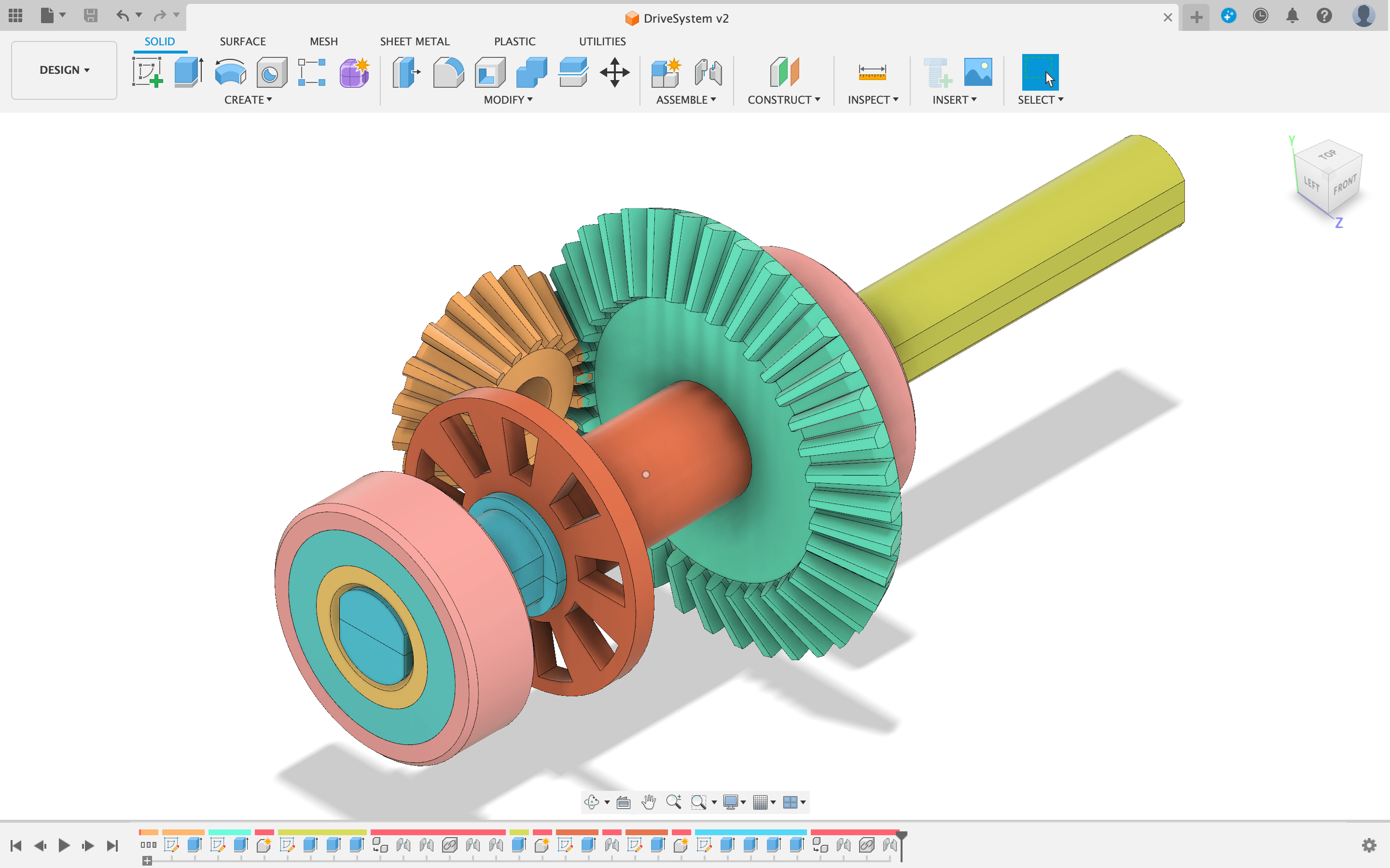
I am going to use two of the cordless drill-brushed 12 V motors on our PiWars robot, one on each side to drive the tracks, to keep the width of the robot down, and the centre of gravity low, the motors will be mounted longitudinally low down in the centre of the main body between the tracks, with the drive being taken from the motors through a 90-degree angle using 3D printed bevel gears.
I am probably going to use the remaining 12 V motor and the two 18 V motors in my remote control K9 project.
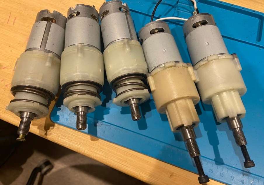
The 12 V motors have their clutch system ring still in place, so I don’t need to override the clutch mechanism, and since the robot is to be driven by my son, and perhaps even my 3-year-old daughter, it would be wise to have back-drive and clutching as protection for the transmission system.
The clutch system decouples the motor from the output shaft when the torque is too high, this prevents damage to the drive train if the output is stalled. The clutch is a ball detent clutch. A spring presses ball bearings into notches to engage the drivetrain. When the torque overpowers the spring, the balls pop out of the notches, and the clutch slips. The compression on the spring can be adjusted by turning a ring to either compress or release compression on the spring, the higher the compression the more force that can be transmitted before the clutch slips.
The two 18 V motors are missing their springs, ball bearings, and spring compression device, to lock out the clutch, you insert bolts into the holes where the ball bearings would be.
Gear Train gears
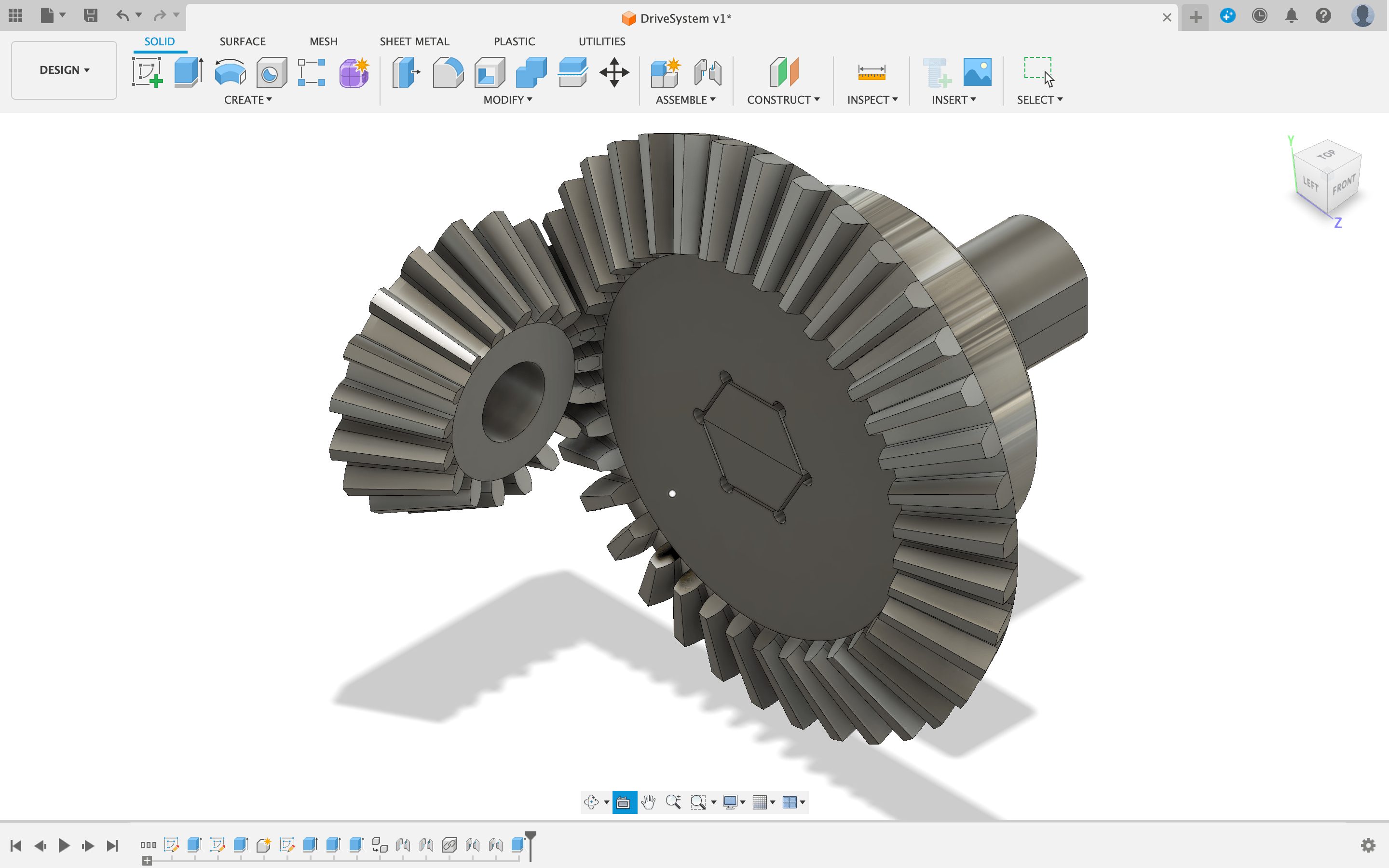
To design the gears in Fusion 360 I am using a plugin called GF Gear Generator, My two gears are designed to have 17, and 37 teeth. With a 1 mm module.
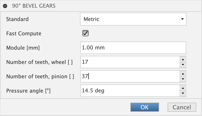
Gear plugin is called GF Gear Generator, the two gears are designed to have 17, and 37 teeth, with a 1 mm module.
Both 17, and 27 are prime numbers, they were chosen to minimize the wear of the individual teeth, due to the number of meshings of the same pair of teeth being minimized (once each 169 revolutions). The gear ratio of 17:37 is near enough to a halving of the output speed (doubling of torque).
The 1 mm module was chosen to allow easy 3D printing.
Motor Driving
To Drive the motor I am going to use an H-bridge until I design my own FET-based H-bridge, I have some L298N pre-built modules. The L298N has a single channel Peak output (non-repetitive) of 3 A, with a 2 A steady state. I will be using two L298Ns, one for each motor, using both channels on each to control the motors, this allows for 6 A inrush, and 4 A steady state. The 12 V drill motor is an RS-550 motor, the specification of which is
- Nominal Voltage: 12 V
- No Load RPM: 19300
- No Load Current: 1.4 A
- Rated RPM: 17100
- Rated Torque: 0.055 Nm
- Stall Current: 85 A
- Stall Torque: 0.459 Nm
Because the L298N (and the L298HN, and L298P) are transistor-based H-bridges, they need to dissipate the 0.7 V transistor drop (1.4 V drop due to there being two transistors in the path) as thermal energy. which is where the power limitation comes in. Using FETs (Field Effect Transistors) would remove this voltage drop, and associated power dissipation, allowing for more current to be drawn through the motors.
To manage the current draw through the H-bridge I will use a shunt on the low side of the bridge, that allows the current to be monitored by the microcontroller that is driving the H-bridge, on the below diagram these are marked as Sense A and Sense B.
A H-bridge is an electronic circuit that looks like the letter H. An H-bridge is used to drive a load, such as a brushed DC motor, in both directions, the external components required for the L298N to operate are four diodes per bridge, and a few capacitors. Rsa and Rsb resistors are optional and are only required for current feedback.
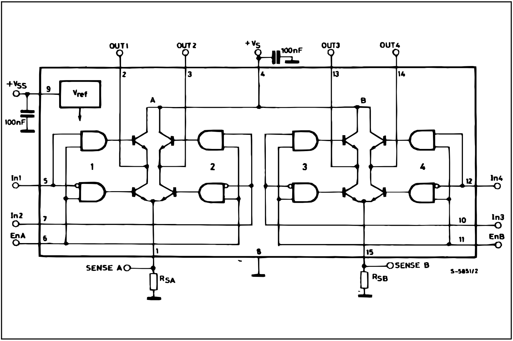
Vs is the supply voltage for the motor, The L298 is rated for a maximum motor supply of 50 V, with a DC load drawing 2 A steady-state output, this means that the maximum power that can be supplied is 100 W. with a power dissipation via the transistors of about 2.8 W thermal. With a Vs of 12 V DC, the maximum motor power available is about 24 W.
The supply Vss (Logic Supply Voltage) is designed to receive between 4.5 and 7 VDC, with a nominal supply voltage of 5 VDC.
In1, In2, EnA, In4, In 3, and EnB will fully saturate (be fully turned on) with a voltage of about 2.4 V applied to them (information from the datasheet), so will work using a 3V3 microcontroller.
While the motor drive system is not going to be the main controller, of the robot, I have not used the RP2040 for any projects yet I will try and build the motor controller around an RP2040 Stamp.
Motor Feedback
In addition to getting feedback using the two shunts (resisistors) RsA and RsB on the low side of each of the bridges, I am going to use optical infered interruption sensors to detect the rotation of the output shaft.
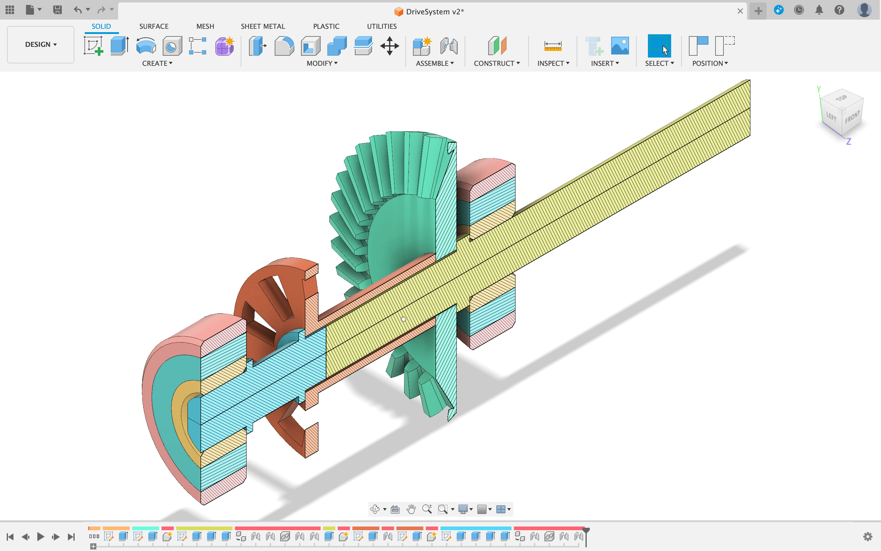
The output shaft is made up of four pieces, allowing them to be 3D printed in a stronger orientation, without the need for over hangs, or support, the four shaft pieces will be glued together for strength.
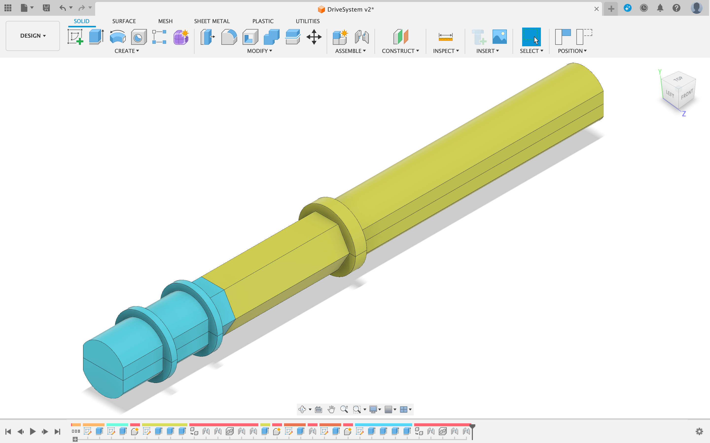
The square sided circle profile on the ends has been chosen to allow for drive wheel on the tank tracks. to spline onto it, while still allowing for the shaft to pass through L6008ZZ bearings for support. the hexagonal profile in the center has been chosen to spline into the drive gear and the optical detection ring.
The split in the shaft between the blue, and yellow above allows for the bearing and other retention features to be aligned.
I will print out a test assembly, and work on interfacing the small pinion onto the drill motors.


6 thoughts on “Drill motors for our PiWars Robot”
Great idea
Keep up the impressive work
Good luck with the drill motors and L298 drivers! We (@Hitchinhackspace) tried drill motors with tracks for our first Pi Wars entry, with ~10A motor controllers ( https://hackhitchin.org.uk/pi-wars-drivetrain/ ). They were ridiculously quick, powerful and current hungry. 85A stall motors on 2A controllers!? And 1.4A of those 2As is just being used to overcome friction in the gearmotor? I think the motors, with the gearing you’ve got planned, could work fine, but I’m fairly sure you’ll need a motor driver that can handle more current .
Thanks for the response Mark,
I am aware that the drill motors and the H-bridges are badly matched! if not to say VERY badly matched.
In mitigation I am going to use two of the L298s, one for each motor, with the two bridges in parallel. not to mention a nice bit of aluminium for them to be pressed up against, With a PT100 or two (for thermal profiling), as well as the shunt resistors giving me the current feedback.
And all this is only until I have my nice FET based H-bridge up and running.
My guess is that the driveshaft will get shredded/snap.
I’d suggest making a square hole down the middle and put a length of bar down it.
I will try it this way, and if it needs be fall back to a square rod, with flanged spacers to run it true in the bearings.
Square rod also simplifies the splining of the gear to the rod.