Relays are a kind of electrically operated switch that opens and closes the circuits by receiving electrical signals from outside sources.
In this post, we are going to look at mechanical relays. Relays receive an electrical signal and send the signal to other equipment by turning the switch on and off.
We will cover Contactors, Solid State Relays, and Flyback diodes at a later time.
A mechanical relay consists of a coil, which receives an electric signal, converts it to a mechanical action, and contacts that open and close the electric circuit.
One of the significant characteristics of a mechanical relay is the physical spacing between the coil and the contact component in order to achieve an appropriate level of insulation (insulation distance) on both input and output.
One of the other significant characteristics of a mechanical relay is that the coil and the contacts can operate at different voltages, for example, it is not unusual to have a relay with a 5 V coil, driven by a microcontroller.
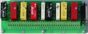
Different types of relays
In general, the nomenclature for relay contact layouts is about the configuration of the contacts in the relay, and the number of sets of contacts.
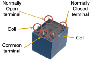
The coil will have two terminals, sometimes marked as A and B. in most instances it does not matter which way round these are connected, or if you apply AC or DC to them, however, some relays have a built-in flyback diode.
Normal coil voltages for small relays are 5, 12, and 24 VDC, but more specialist applications may have higher voltages. it is important to check this when you are using a relay in your application.
The other three terminals called out on the image to the right are:
- The Common terminal (COM), this terminal has its connection changed between the normally open terminal (NO) and the normally closed terminal (NC).
- The normally open terminal (NO) is not connected to the common terminal when the coil is not energised, on energisation, the COM is connected to the NO.
- The normally closed terminal (NC) is connected to the common terminal when the coil is not energised, on energisation, the COM is disconnected from the NC.
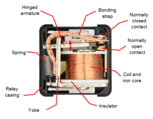
The image on the left shows a “1 Form C” automotive relay that has had part of its cover removed.
The common contact is attached to an armature that pivots around the yoke and is retained against the normally closed contact by a spring. The passing of current through the coil wrapped around the iron core causes the armature to rotate towards the normally open contact due to the magnetic attraction between the armature and the coil. The bonding strap makes sure that the common contact is bonded to the common pin.
Removal of the current from the coil removes the magnetic attraction, and the spring causes the armature to move back.
It is normal to draw relays as though the coil is in a de-energised state.
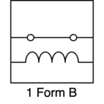
1 Form B relay
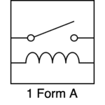
A “1 Form B” relay has one set of contacts, with them being in the normally closed position, applying current to the coil terminals disconnects the COM and CO terminals preventing current from flowing.
1 Form A relay
A “1 Form A” relay has one set of contacts, with them being in the normally open position, applying current to the coil terminals connects the COM and NO terminals together allowing current to flow.
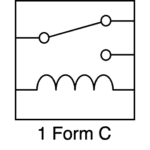
1 Form C relay
A “1 Form C” relay has one set of contacts, however, it has three contact terminals instead of just the two shown in 1 form A, and 1 form B relays above.
When current is not applied to the coil, the COM terminal is connected to the NC terminal, and the NO terminal is disconnected.
When current is applied to the coil and it is energised the COM terminal is connected to the NO terminal and the NC terminal is disconnected.
It is normal to draw relays as though the coil is in a de-energised state.
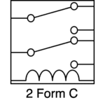
2 Form C relay
A “2 Form C” relay is the same as two “1 Form C” relays in the same package sharing a common coil, they generally draw slightly more current to move the contacts between the NC and NO.
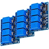
You can buy relays online, including sites like amazon, here is a listing for three 4×1 Form C relay boards with an optocoupler for direct driving from an Arduino, STM32, Raspberry Pi or similar, however, I would take the rating printed on the top of them with a large dose of scepticism. I would recommend only using them for prototyping.
Omron, Picker or Pickering are names of relay manufacturers I trust, you can buy them via Farnell or similar.
We will cover Contactors, Solid State Relays at a later time, and Flyback diodes. I will also write a post on Snubbers and snubbing contacts, as well as how to drive relays safely.
Also, I will write a post about Automotive relays as it relates to my automotive wiring post.


12 thoughts on “Learn about Relays”
That photo looks like an old Opto88
The coil voltage is important – most relays like this cannot be driven directly by an Arduino output. You may need a darlington driver such as the UML2004 if you are controlling multiple relays.
I have touched on that previously, however, I will explicitly write a post soon.
Until then, this post should be a good starting point:
The notation “2 form C” isn’t in any way normal (normal is SPST, DPDT etc). And the fully shrouded screw terminals are suitable for 240V European mains power.
Single pole single throw etc to describe switches. SPST doesn’t tell you the nominal state of the contacts.
I assume that you do not read datasheets often?
As for the 5mm pitch screw terminals. How do you meet the requirements of creepage and clearance as required by the Low Voltage Directive?
That is ignoring the 8mm wire test.
don’t forget the diode with kathode to vcc on the coil side, anti parallel over the coil, to prevent induction when switched off , this peak will reacht reach 650v and blow up transistor.
I have mentioned the flyback diode in the article above.
and do not forget that every GPIO on Raspberry Pi Pico is 3.3V only
Don’t forget to include a diode in parallel with the relay coil to protect the microcontroller.
I have mentioned the flyback diode in the article above.
Rather than designing your own transistor driver and protection circuit etc, don’t we all normally use the pre-made opto-coupled modules that are eventually mentioned at the end of the article? Why is the author scathing about them?
The relays I use the most are:
Most of these cheap opto-coupled modules use a QC-3FF-S-Z or similarly labelled relays (The relays on the above board don’t even have that printed on them). Also the 5mm pitch screw terminals that they use are not suitable for anything other than SELV voltages.