In a previous post, I talked about the MCP23017 and MCP23018, and why the MCP23017 was a better device for my use in this case (this case being my Remote control K9).
The MCP23017 can only output a digital high of the same voltage as VDD, which is capped at about 5 VDC (the exact value will be in the datasheet). However, I want to drive incandescent bulbs, which require about 12 VDC to illuminate them, so to drive these I will be making use of a number of the ULN2803:
The ULN2803A device is a 50 V, 500 mA Darlington transistor array. The device consists of eight NPN Darlington pairs that feature high-voltage outputs with common-cathode clamp diodes for switching inductive loads. The collector-current rating of each Darlington pair is 500 mA. The Darlington pairs may be connected in parallel for higher current capability.
Applications include relay drivers, hammer drivers, lamp drivers, display drivers (LED and gas discharge), line drivers, and logic buffers. The ULN2803A device has a 2.7 kΩ series base resistor for each Darlington pair for operation directly with TTL or 5-V CMOS devices.
ULN2803 Datasheet
This 500 mA at up to 50 VDC compares with the MCP23017s 25 mA at 5 VDC.
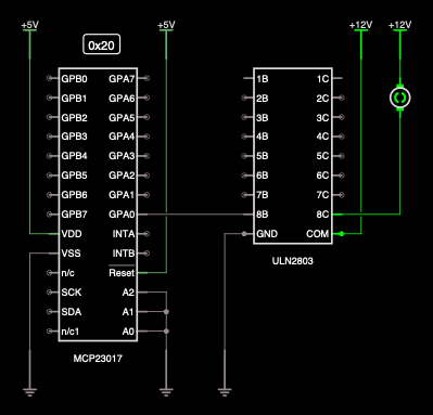
In the image to the right, I show the two devices connected together with just channel GPA0 connected to 8B (Base), and a brushed DC motor is connected between 12V DC and 8C (collector).
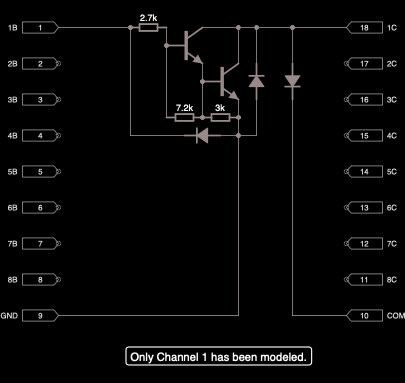
Internal to the ULN2803 is a Darlington pair, a flyback diode and some support passives for each channel. the flyback diode protects the components when using the device with inductive loads, such as motors, coils, or relays.
In this instance, I am using the ULN2803 to switch on and off 12 x 12 VDC incandescent bulbs mounted in switches.
I am going to use two ULN2803s driven by one MCP23017. This will give me 16 channels. I could use low-side switching with a single N-FET of a Darlington pair made up of discrete components, however, this component makes the circuit much more straightforward.
The ULN2803 is very similar to the ULN2003 but has eight outputs rather than seven.
A quick warning!
When using different supply voltages, ensure that the ULN2803 or ULN2003’s common pin is taken to the supply of the load. If you don’t you may find the flyback diode allows enough current to flow, meaning that the load is turned on regardless of the input state.
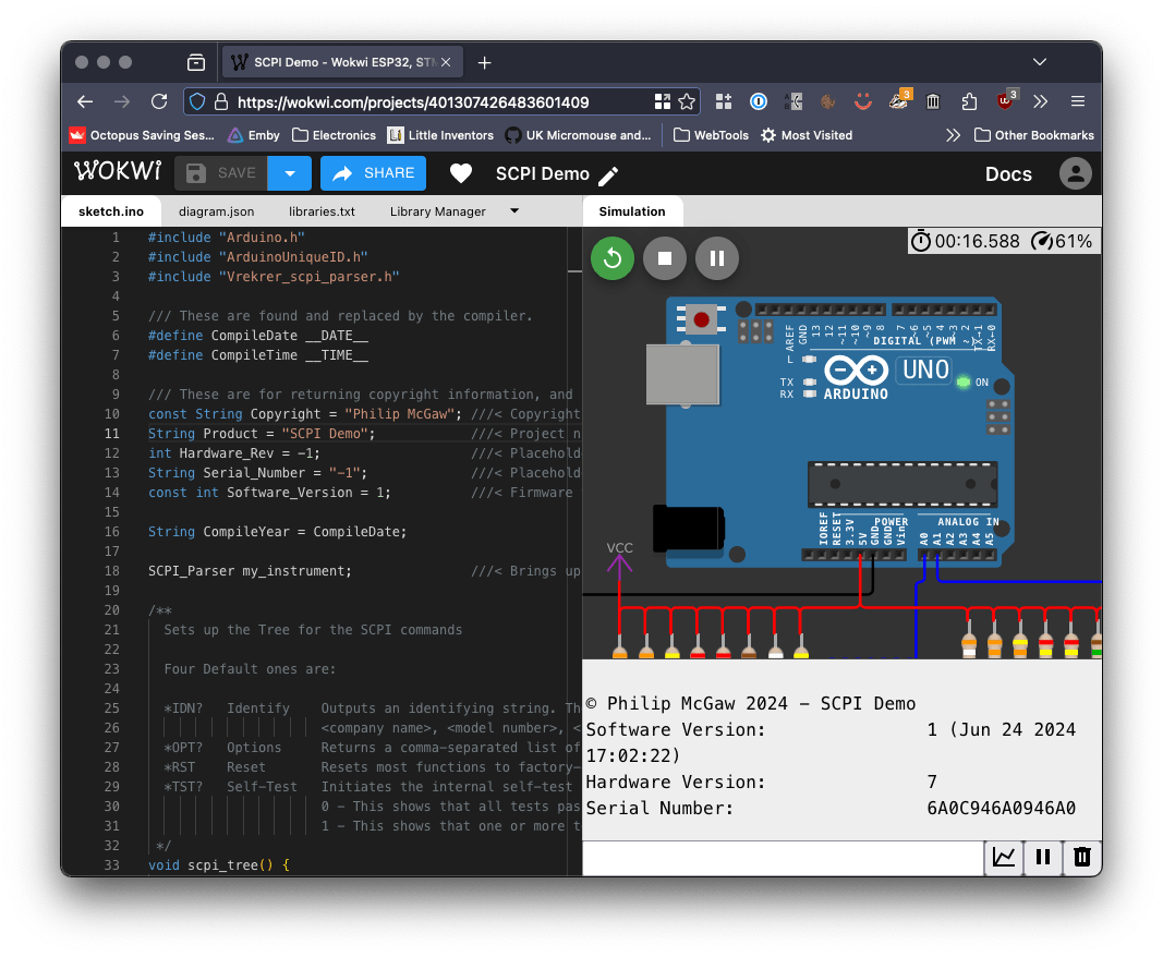
In a future post, I will put this all together with an Arduino and a 3D-printed button enclosure.


12 thoughts on “MCP23017 and ULN2803”
You can connect the io expander directly to the Raspberry pi, if you want
I am aware of this, however, I want to keep the length of the I2C to a minimum, and I am happy to use USB to modularise the system.
Interesting! Just curious, why do you want to use 12V incandescent bulbs for the control panel lights?
It’s what the switches I bought a long time ago came with
Yes, if we’re talking about the actual K-9s used on the TV show I’m sure they used incandescent bulbs because that’s all they had available back then, whether they used 12v or 6V incandescent bulbs is a question for the experts. Of course, they didn’t have Arduinos or RPis either.
It’s just the switches I could buy at the time had 12 VDC incandescent bulbs.
I will have more details of the Arduino shield for the back buttons on my site soon.
The switches I used in my first K-9 came with incandescent bulbs as well but I swapped those bulbs out with LEDs, I wrote a “how-to” and posted it on WhoProps…
https://whoprops.proboards.com/thread/355/control-panel-light-led-conversion
I have done it before https://skippy.org.uk/re-bulbing-k-9s-back-buttons/
What is the magic you are using to convert 12v directly to 5v without a regulator?
The 12 VDC to 5 VDC regulation is outside the scope of this diagram, the 5 and 12 VDC rails are just that, voltage rails.
On your diagram they look connected
They don’t look so connected to me.