
I can’t quite remember how long I have been interested in seeing what is under the water, I have been writing my thoughts about building an ROV on my old site for a while.
I picked up a copy of the book, “The ROV Manual – A user guide for observation class remotely operated vehicles” by Robert D. Christ and Robert L. Wernli Sr.
The book gives a lot of background about the different types of commercial ROVs,
ROV systems come in three basic categories:
The ROV Manual
- Observation class – Observation-class ROVs are normally a ‘flying eye’ designed specifically for lighter usage with propulsion systems to deliver a camera and sensor package to a place where it can provide a meaningful picture or gather data. The newer observation-class ROVs enable these systems to do more than just see. With its tooling package and many accessories, the observation-class ROV is able to deliver payload packages of instrumentation, intervention equipment, and underwater navigational aids, enabling them to perform as full-function underwater vehicles.
- Work class – Work-class systems generally have large frames (measured in multiple yards/meters) with multi-function manipulators, hydraulic propulsion/ actuation, and heavy tooling meant for larger underwater construction projects where heavy equipment underwater needs movement.
- Special use – Special-use ROV systems describe tethered underwater vehicles designed for specific purposes. An example of a special-use vehicle is a cable burial ROV system designed to plough the sea floor to bury telecommunications cables.

From this, it is obvious that I am going to be working on building an Observation class ROV.
Since starting looking at this, OpenROV has been launched and they also have launched their second project the OpenROV Trident. As well as the CPSdrone project.
My ROV
I will write up where I have got to, and detail the technologies used so far in the construction of this project. including some of the maths that I have utilised to generate the requirements.
While I am not going to offer this as an Underwater ROV Kit for sale, everything I am working on will be available online (via GitHub) as an open-source project.
I have also put together a page that gives an overview of this project and should have the current details of what I have managed to achieve.
While my ROV will not be a “drone” in the same way as a quadcopter is a drone, It will be a remotely controlled robot with a camera allowing an operator to navigate underwater, and hopefully, take some good videos.
I have put together the following overview of the system architecture from a hardware standpoint.
High-Level Overview of ROV System Architecture
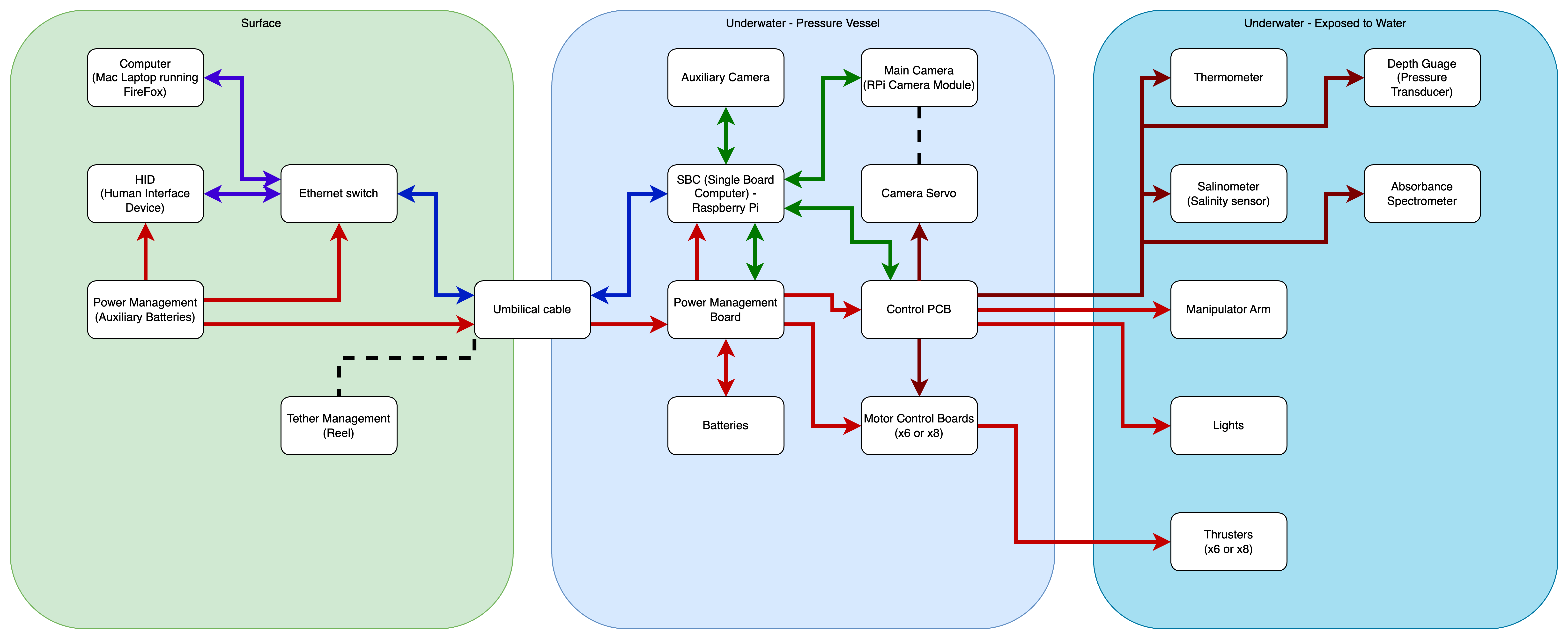
Surface
On the surface there is going to be at least one laptop computer running a web browser (in my case probably Firefox), connected via ethernet to the ROV through the umbilical. the HID (Human Interface Device) will likely be a joystick with some extra input devices to allow manipulation of the camera and other IO devices on the robot.
Also on the surface will be a Power Managment module, made up of 2 x 10S2P Lithium Ion batteries with a nominal voltage of 37 VDC, that will supply power to the topside equipment, and auxiliary power via the umbilical to the ROV.
Underwater – ROV Pressure Vessel
The ethernet will terminate in to a Raspberry Pi SBC (Single Board Computer) where software will be running to allow for control signals to be broken out to a control PCB. and the two camera feeds (more cameras may be able to be added in the future) will be brought up to be sent back to the top side computers.
The Power Managment board will take the 36 VDC from the tether, as well as the power from the local batteries and distribute it to the SBC, Control Board, and the Motor Control Boards (ESCs).
The Power Management board will also report on the status of voltage levels and current draws to the SBC via UART over USB (Virtual Com Port).
The Control PCB will communicate with the SBC as a Virtual Com Port, and send speed, and position data to the ESCs and the main camera servo. The Lights and Manipulator Arm will be dedicated circuits. The Control PCV will also interface via I2C to the various sensors outside the pressure vessel.
Underwater – Exposed to the water
I2C transducers will be exposed directly to the water, physical properties such as Tempriture, Depth, Salinity and spectromitory data will be measured and reported back via the I2C to virtual com port on the control PCB.
The lights are going to be based on white LEDs, the design and format is to be confirmed.
Passive provision is being made for a Manipulator Arm, again like the lights, the design and format is to be confirmed, this could also take the format of an easy to swap out part.
Their are either going to be six or eight thrusters, these have had early design work done on them, and will be the subject of a post soon.


13 thoughts on “DIY underwater ROV”
Hola buenas tardes,observo en el esquema que la imagen la proporciona una camara USB conectada a Raspberry que lanza la imagen hacia “arriba” ,es una configuracion que se repite en muchos ROVs,yo no la he probado,pero me da la impresion de que esta bastante limitada tanto en calidad de imagen como en numero de camaras .
Por mi parte llevo mucho tiempo con un diseño muy distinto en el que uso una GoPro y un codificador de HDMI a Ethernet 264/265 y a traves de un PLC saco la imagen a la superficie por medio de un unico par trenzado sin que intervenga ningun ordenador en el interior del casco de esta forma no tengo nada de LAG y obtengo calidad GoPro para la imagen y ademas puedo conectar varias camaras simultaneamente.Solo lo he probado sobre la mesa ,espero tener conclusiones mas amplias en breve. Uso un ESP32 en el casco sumergido y un Arduino Mega en superficie para la comunicacion de ordenes a motores y parametros generales ,el programa de control lo he escrito yo mismo ¡¡la proxima semana espero probarlo en la piscina!!
Google Translate tells me that you wrote the following Josera:
That sounds Intresting, I would like to know more about your setup 😀
Nah I have one sitting right here laying beside me, I might get rid of. unless you’re out of the states. on sourcing one.
I am in the UK.
Wow that’s awesome!
amazing work 🙂
Thank you 🙂 the next post should be out today or tomorrow depending on how I get on with the maths 🙂
I wonder how this would work with the Begalbone blue instead of a pi?
Probably quite well, but the Beglebone Blue is a very old board, and chances are I would have even more difficulty sourcing one than I would have using a Raspberry Pi.
Thank you, this is amazing
Thank you 🙂 the next post should be out today or tomorrow depending on how I get on with the maths 🙂
If I ever build an ROV, I’m going to buy the software from Bluerobotics.com. Try to buy anything rather than build it.
I do like the look of the BlueRobotics products.