
You may have heard the saying “never trust the autorouter”, you may have even seen it written on a t-shirt!
Back when I used Eagle ECAD (Before AutoDesk did their thing), there was a built-in autorouter that was a handy tool to use to help with working out if you could hand route a PCB, or if something in the layout would make it impossible (or at least difficult to route).
KiCAD doesn’t have an auto-router built-in, there is an external tool called FreeRouting, It can be downloaded from https://freerouting.mihosoft.eu/
Once the file has been moved into the applications folder from the .dmg it is installed, however, you may get a prompt informing you that the application is damaged and you need to delete it, the way around this is in terminal:
cd /Applications/
sudo xattr -cr Freerouting.app
PCB
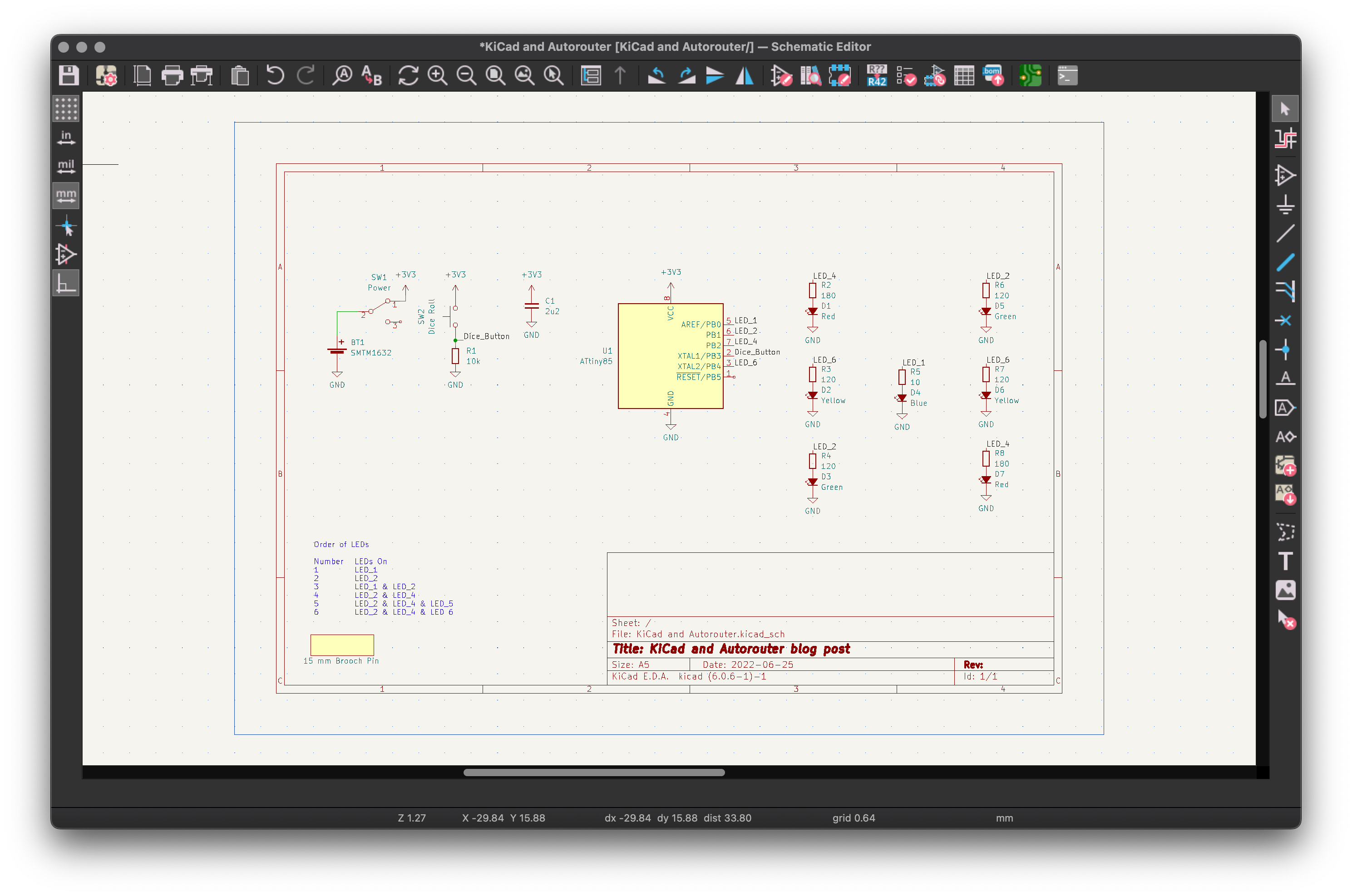
For this blogpost I am going to place the following components on a schematic:
- 1 x 10 Ω 0402 resistor (Resistor_SMD:R_0402_1005Metric_Pad0.72×0.64mm_HandSolder)
- 2 x 120 Ω 0603 resistor (Resistor_SMD:R_0603_1608Metric_Pad0.98×0.95mm_HandSolder)
- 2 x 120 Ω 0805 resistor (Resistor_SMD:R_0805_2012Metric_Pad1.20×1.40mm_HandSolder)
- 2 x 180 Ω 1206 resistors (Resistor_SMD:R_1206_3216Metric_Pad1.30×1.75mm_HandSolder)
- 1 x 10k 1206 resistors (Resistor_SMD:R_1206_3216Metric_Pad1.30×1.75mm_HandSolder)
- 1 x 2u2 1206 chip capacitor (Capacitor_SMD:C_1206_3216Metric_Pad1.33×1.80mm_HandSolder)
- 1 x Blue 0402 LED (Diode_SMD:D_0402_1005Metric_Pad0.77×0.64mm_HandSolder)
- 2 x Green 0603 LEDs (Diode_SMD:D_0603_1608Metric_Pad1.05×0.95mm_HandSolder)
- 2 x Red 0805 LEDs (Diode_SMD:D_0805_2012Metric_Pad1.15×1.40mm_HandSolder)
- 2 x Yellow 1206 LEDs (Diode_SMD:D_1206_3216Metric_Pad1.42×1.75mm_HandSolder)
- 1 x pre-programmed ATtiny85 MCU (Package_SO:SOIC-8W_5.3×5.3mm_P1.27mm)
- 1 x SPDT switch (Button_Switch_SMD:SW_SPDT_PCM12)
- 1 x Push to make switch (Button_Switch_SMD:SW_Push_1P1T_NO_CK_KMR2)
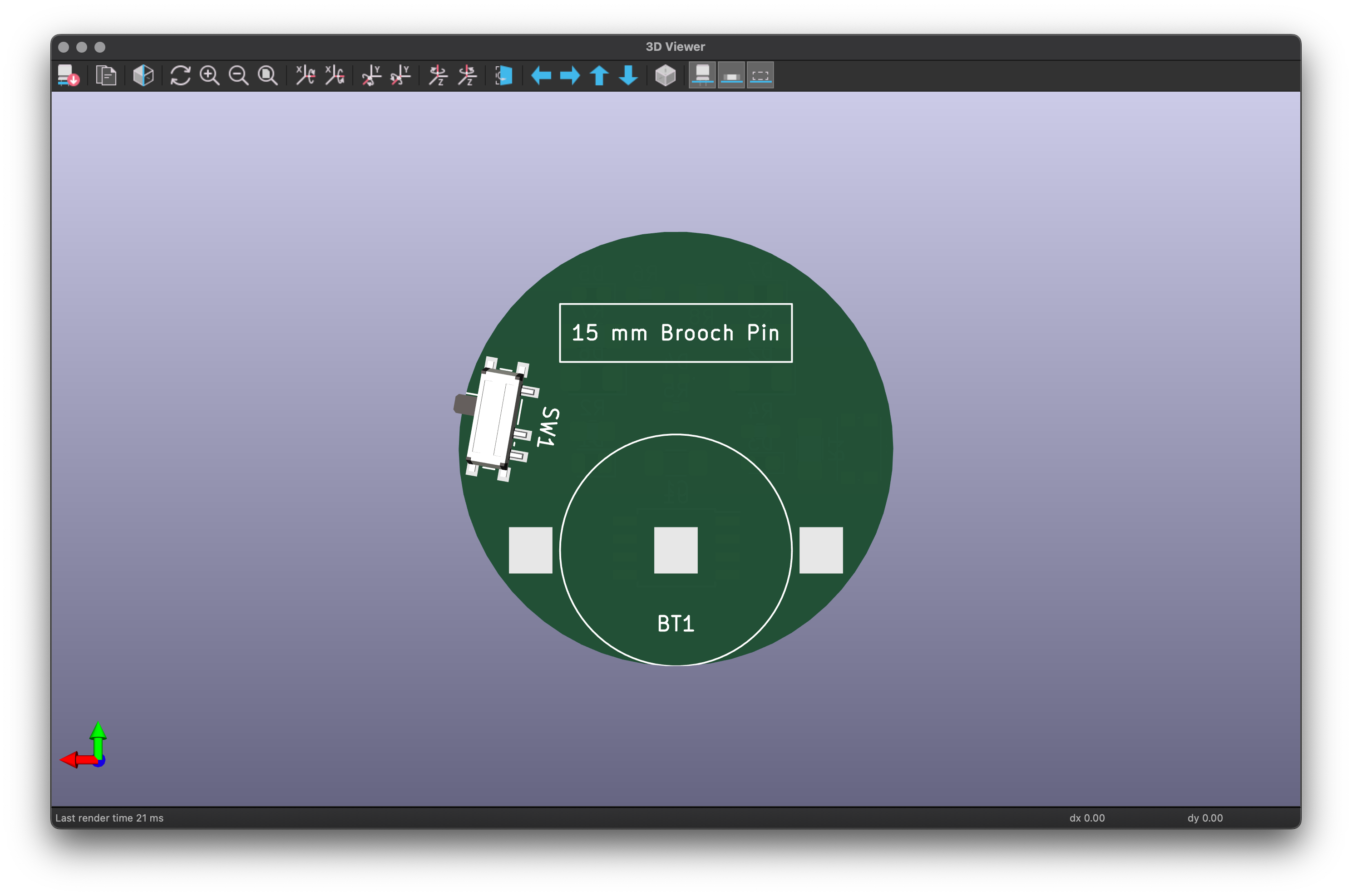
- 1 x 15mm brooch pin
- 1 x battery clip (SMTM1632:SMTM1632)
The battery chosen for this is a CR1632 coin cell, wiring them up to make a dice badge, that uses the ATtiny85 to play a pattern when left alone, but when the push button is pressed it will display a random dice number.
The text in blue in the lower left-hand corner of the schematic explains which LED sets need to be enabled to display numbers.
Laying the components out on the PCB editor so they fit on a circular 30 mm PCB, with ground fill on top and bottom copper gives me the following rats nest to resolve. At this point, there has been no optimisation of pins, or component orientation.


Now we have the components where I want them placed, I can now move on to having the autorouter have a go at cleaning up the ratsnest
Exporting a DSN file File > Export > Spectra DSN saving the file as Ratsnest.dsn, so I can feed it to Freerouting…
Freerouting
Running Freerouting from the applications folder (if you get an error saying it is damaged, the instructions for fixing it are near the top of this page), and opening Ratsnest.dsn gives the following on the screen:
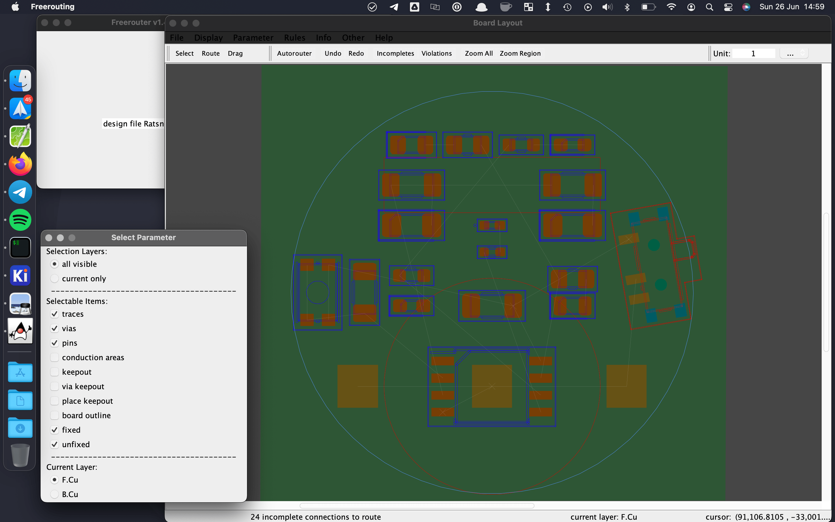
On the top bar is a button marked Autorouter that you press to let it have a go,
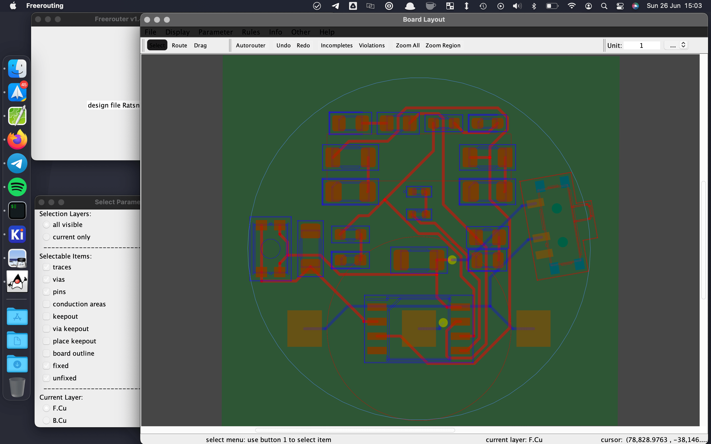
Every time you click the Autorouter button it will generate a different solution, so if you are not a fan of the output you can run it again until an acceptable solution is returned. this is a fairly simple board so I was not expecting to run into any issues, however, had it been unable to route it taking what I saw from the auto-router back into the schematic capture, or the PCB layout software, I could move some of the components around, or performed a pin swap on the microcontroller.
And back into PCB Editor
Once you have a route that you are happy with, in Freerouting File > Save and File > Export Specctra Session File, it will ask you if you want to save the rules, I go with yes, as I don’t see a downside to this, and they may be useful at some point.
Back in PCB Editor File > Import > Specctra Session… and the screen will re-draw, you will want to press b to redraw the fill. Some new ratsnests will appear as the ground plain is no longer contiguous.
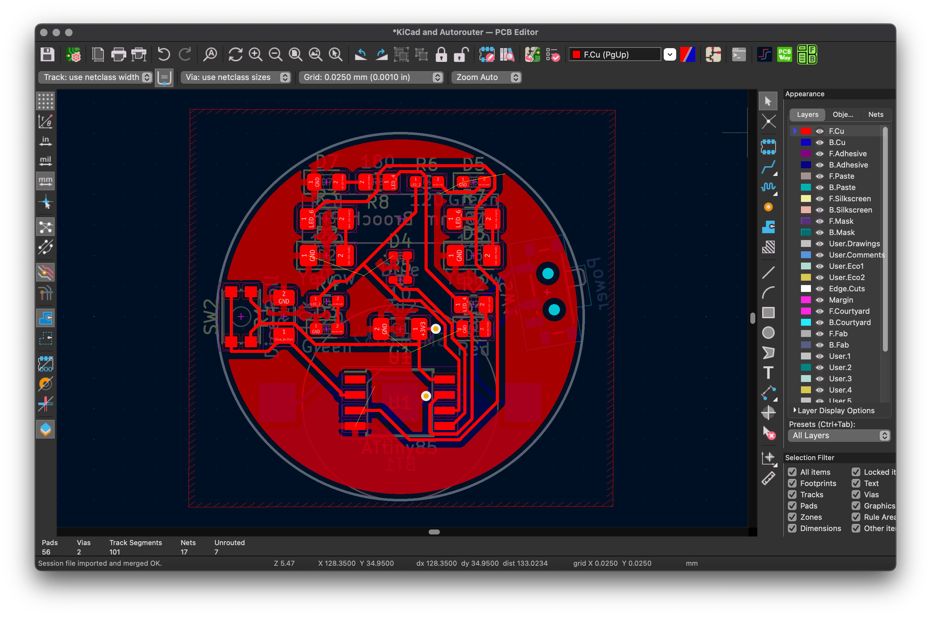
A little bit of cleanup later, and some more vias on the ground plane and we have a valid PCB:


Can I trust the Autorouter?
Well yes, but make sure you know what you are doing, and understanding and knowing its power and limitations will give you another tool for when you do PCB design.


15 thoughts on “KiCad and the Autorouter”
Having used PCB layout software with AutoRouters, I found that it was useful as a hint device. Some of my designs were started with manual routing, some autorouted tracks, that were either ripped up again for more manual routing, or adjusted. It was never ever place components and hit autoroute for any design.
It was always ‘never trust without verification’.
The Autorouter is great for letting you know if your design can be routed, not really up to doing it for you.
When routing a PCB layout, manual or semi-automatic via fanout is important. A good technique is to place parts and get EE or management approval. Then fannout every SMD pad. Copper pour Layer 1 with GND or multiple split GNDs. Copper pour the Bottom layer with VCC or multiple split VCCs. Use the inner layers for routing signals.
Why? Because the outer layers are 1.5 OZ copper and the inner layers are usually 1/2 OZ copper. The inner layers have minimal obstacles for trace routing. Don’t trust the outer layers for clean return paths especially if they are split.
Add inner GND layers so that every signal layer is next to a GND layer. GND, Signal, Signal, GND is the pattern.
I tend to do most of my work on two layers, Four if I need more complexity
For 2-layer designs do you use coplanar technology where the outer layers are GND copper pour in-between traces? Then stitch the GND pours together with vias? Route all the VCC. What’s your technique for signal return paths?
Copper ground pour on both top and bottom, I try to reduce Islands as much as possible, and at least two vias for every contiguous copper area.
Power traces I am aiming for as short and direct as I can possibly manage, with decoupling caps near to anything with an in-rush current.
Where can I buy this t-shirt?
There is a link to the T-Shirt above – https://contextualelectronics.com/product/never-trust-the-autorouter-t-shirt/
If you have a great CAD tool like PADS Professional (which is only $2,999 a year), the interactive route editor is so powerful that it is very similar to an autorouter. It’s a sketch router that is controlled by the user and obeys all the design rules you create. Pays for itself in a couple complex designs. I wouldn’t recommend PADS Pro if your PCB designs are simple layouts. I would recommend KiCad for simple layouts. A high percentage of PCB designs are simple.
ohhhh please!, at work they have PADS professional with two senior engineers doing the layout work for several years now, they were sooooo slow and the tool itself also was not up to the task that I ended up doing my own PCBs which are not so simple (16+ layers FPGA designs) directly in KiCad having a faster turn around and not having to constantly wait for the tool every time you click on something, it was very sluggish and our PCs are top models nowadays. Also, just simple things like creating multi-symbol parts or length tuning was much faster/easier in KiCad. Having said that, hyperlynx was actually useful, but I think one can export now from KiCad to that for analysis.
I used the Tango (Accel) autorouter back in the late 80’s and it was fairly reliable (on smaller circuits at least). My number enemy these days is auto placement – it never places anything where I want it.
I haven’t given auto-placement a try, I tend to have outside constraints on the locations of components.
I don’t believe the advanced connection methods are capable in KiCad yet.
*VeCS structures.
My answer is no, never trust, or even better, never use any kind of auto-router. I have a thought that if you use auto router, you have no idea of how to do alayout. At the end, you don’t know your board, and if you need to do a hardware debug, you’ll have a tremendous difficulty to do or waste a lot of time do to.
If you any time need to use or would like to use, use only to check if the placement is OK, but delete all the tracks after that and manually route them. Always make sure you route and checked 100% of the tracks, connections, and vias.
The last part of the post was my writing “Can I trust the Autorouter?
Well yes, but make sure you know what you are doing, and understanding and knowing its power and limitations will give you another tool for when you do a PCB design.”