Following on from my post in AC Rectification, where we took AC and rectified it to a positive-only voltage, we ended the post with 100% peak-to-ground ripple. We will now look at Reducing Ripple on the DC line as much as possible.
I will use the same basic circuit, that is being simulated in Falstad which runs in the browser, and add Capacitive and Inductive components to the full-wave rectified bridge rectifier circuit below.
powered by Advanced iFrame. Get the Pro version on CodeCanyon.
I have added two traces to the scope, the two new red lines represent the source voltage and current, the red trace with an amplitude of about 1.4 V greater than the green trace is the source voltage, the other red trace with a lower magnitude is the current being sourced from the source, while the load side of the bridge rectifier is resistive only there is no deviation from a sinusoidal wave.
Adding a Single Capacitor
powered by Advanced iFrame. Get the Pro version on CodeCanyon.
Adding in a single 10 μF capacitor to the circuit in parallel with load resistor means that the voltage on the load side doesn’t drop to zero (green trace) and using ohms law we can see that the current through the resistor (yellow) tracks the green trace.
While the Source voltage is still a sinusoid the source voltage rapidly rises when the voltage on the output side of the bridge rectifier is greater than that of the capacitor, and falls as the capacitor charges, the current falls back to zero once the source voltage is at its maximum magnitude as the capacitors now fully charged and the voltage on the secondary side is higher than the output voltage of the bridge rectifier.
Changing the value of the capacitor will change the amount of ripple that the capacitor can reduce.
Adding a Single Inductor
powered by Advanced iFrame. Get the Pro version on CodeCanyon.
I have chosen to add a single 68 μH inductor, This is representative of a TDK SLF10145T-680M1R2-PF inductor, according to its datasheet it can carry 1.2 A before saturating.
As the Current carrying capacity and inductance value increase, so does the physical package size and cost. This 68 μH inductor has a cost of about £1.50 and is about 10 x 10 mm (a 10 μF Kemet EXV106M035A9DAA capacitor above is about 40p and 5 x 6 mm) As you can see from the oscilloscope trace the inductor has very little effect on the ripple current. However, the inductor has EMC filtering advantages.
Adding Two Capacitors and an Inductor for Reducing Ripple
powered by Advanced iFrame. Get the Pro version on CodeCanyon.
We have now added a second 10 μF as well as the inductor, the secondary side current peak is now higher than it was, but the output Voltage and Current ripples now both have a lower magnitude.
Replacing the representative load with a value smaller than 1 kΩ will cause the ripple’s magnitude to increase, adding capacitance will reduce this magnitude.
If the source was a switch mode buck converter (SMP) we could then use a linear voltage regulator or a low dropout regulator (LDO) to reduce the 10 V secondary side to the voltage needed for your circuit.
Reducing Ripple by Regulation Down to 5V
powered by Advanced iFrame. Get the Pro version on CodeCanyon.
This is a very simple circuit for generating an almost ripple-free 5V output from the 10V supply. the use of a Zener diode and a resistor. One of the limitations of the Falstad simulator is that there is no pre-built model for a voltage regulator such as the LM317 or LM78xx family of regulators.
At some point in the future, I will buy a handful of LM317 and LM78xx regulators to build these circuits on a breadboard and prove the simulations.
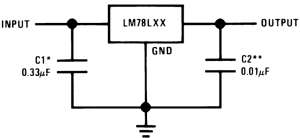
The LM78xx regulator family contains several fixed-value regulators, the LM7805 which is a 5 V fixed output, the LM7806 – 6V, LM7808 – 8V, LM7809 – 9V, LM7810 – 10V, LM7812 – 12V, LM7815 – 15V, LM7818 – 18V and LM7825 – 25V. These devices are capable of sourcing up to 1 A on the output.


