AC (Alternating Current) is used for the transmission of mains voltage, one of its main advantages for use as a method of transmission over DC (Direct Current) is that a change of voltage between High Voltage, Low Voltage, and SELV (Safety Extra-low Voltage) can be performed using a transformer.
- Extra-low. – Not exceeding 50V AC or 120V ripple-free DC, whether between conductors or Earth
- Low. – Exceeding extra-low voltage but not exceeding 1000V AC or 1500V DC between conductors or 600V AC or 900V DC between conductors and Earth.
- High. – Voltages that normally exceed those of Low voltage.
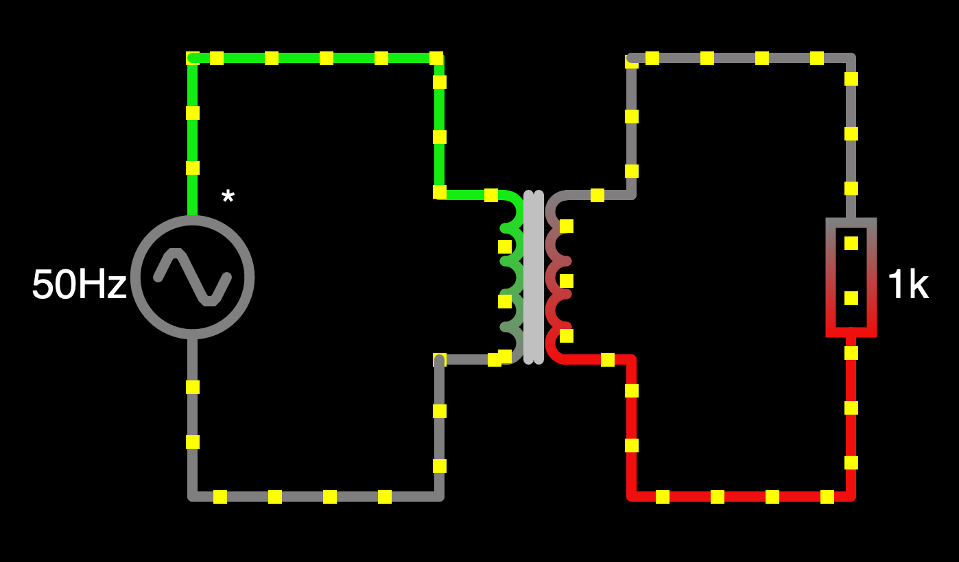
A single-phase transformer is made up of two coils of wire (inductors) on a common core, in general for a given voltage and current, the physical size of the transformer is related to the frequency of the Alternating Current.
While you can change the voltage of DC supplies it requires a more complex set of control circuitry and the losses can be higher than equivalent changes that can be performed on AC. Some other considerations are outside the scope of this post.
powered by Advanced iFrame. Get the Pro version on CodeCanyon.
I have set up Falstad with a 50 Hz 100 V Peak-to-Peak waveform, and a 1:1 transformer, The Green trace on the oscilloscope is the voltage across the source, and the Red trace is the voltage across the 1 kΩ load resistor. By changing the ratio of the number of turns between the primary (source) side, and the secondary (load) you can either increase or decrease the voltage, (current is increased or decreased as a function of the inverse of the voltage). It may be hard to see both waveforms unless you mouse over parts of the circuit as they are almost completely on top of each other.
Simplified circuit
powered by Advanced iFrame. Get the Pro version on CodeCanyon.
This circuit is functionally identical to the secondary side of the transformer circuit above. In this instance the load is purely resistive, so Voltage and Current are in phase, as we can see from the traces below (yellow is current, green is voltage). I will use the below circuit without the transformer to cover rectification as it will reduce the computational load when running the simulations.
Half-Wave Rectification
powered by Advanced iFrame. Get the Pro version on CodeCanyon.
The use of a single diode is enough to remove the negative voltage half of the waveform. The dots represent the current and are set up to show the “Conventional” direction of flow. The diode has a (rule of thumb) Voltage drop of about 0.7 V across it, meaning that with a maximum voltage from the source of 10 V, we see about 9.3 on the output as a minimum, (the simulation shows the output voltage as 9.435 V) this dropped voltage is lost as heat, so for higher current loads, the Diode will be dissipating more heat and thermal management considerations need to be taken as to package sizing and heat sinking.
Half-wave rectification is not considered a good idea, and as you can see the output is off about 50% of the time, with massive amounts of ripple on the supply.
Full-Wave Rectification of Alternating Current
powered by Advanced iFrame. Get the Pro version on CodeCanyon.
With the addition of three more diodes, we can switch up the negative half of the source waveform and now we have no 50% dwell time, we still have an issue with a ripple on the supply to the load, but we will cover how to mitigate that in a post about reducing ripple on DC lines.
This arrangement of diodes is known as a “Bridge Rectifier” Like the single diode above there is a voltage drop associated with the use, in this case, the rule of thumb voltage drop is 1.2 V, and the simulation output shows the maximum load voltage as 8.877 V.


One thought on “Alternating Current Rectification”
You specify the AC voltages you’re using in your diagrams as peak-to-peak voltages.
However, that’s very unusual, as AC voltages are usually specified in Volts RMS, for good reason.
I suspect many, if not most, people on here will not know what an RMS voltage means, why it’s used instead of peak-to-peak voltage, how it is derived mathematically and what the difference is between a peak-to-peak voltage and an RMS voltage.
In my view, this should form a fundamental early part of AC theory, before you even get into rectification.
Otherwise, people won’t understand why a 100VAC RMS voltage, after full-wave rectification, becomes an approximately 140VDC voltage etc, whereas, your 100VAC peak-to-peak voltage, only becomes around 48VDC after rectification.
Furthermore, you state that half-wave rectification “is not considered a good idea”. That’s true at 50Hz, for the reason you stated.
However, it’s not true in general.
Switched Mode Power Supplies (SMPS) such as the ubiquitous phone chargers etc, all use 1/2 wave rectification on their output, because the frequency is so high (50KHz+) that the ripple is very easily smoothed, and hence the circuit is simpler and the production costs are lower.