In my previous two posts, Pressure Vessel and the Viewport, I talked about using the software “Under Pressure” by Deepsea to work out the performance of the Pressure Vessel tube, and the Viewport for my ROV. it’s now time to work out the performance of the end cap which holds the feed-throughs.
The endcap is a simple bit of flat stock that interfaces with the flange and has several penetrations to allow the feed-throughs to carry wires from the pressure vessel to the free-flooded area. There are 10 holes sized for M10 bolts.
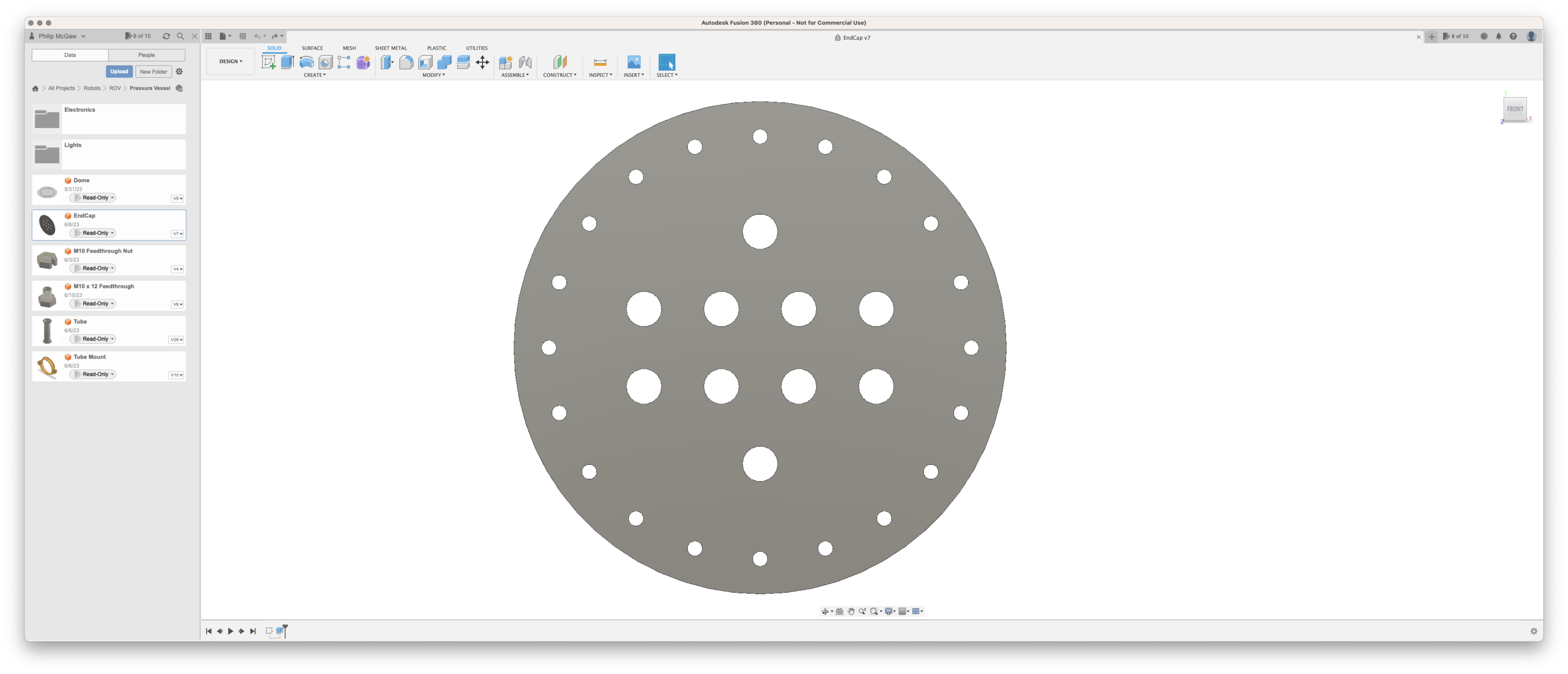
End Cap Material Choices
Since a flat face is subject to more concentrated stresses than a tube, or a hemisphere, the material must be thicker to resist the same pressure.
Since the Pressure vessel is being manufactured out of aluminium, it makes sense to make the endcap out of the same material, especially since I will be machining the flanges out of it too, the mechanical properties of the aluminium 6082-T6 can be found on the pressure vessel page.
Bob Clough, a friend from Manchester will be able to CNC machine these parts for me.
Since I am using a flange on the tube, I am using “Fixed” as the “Edge Restraint Option” with a “Plate Free Diameter” of 100 mm and a “Plate Outside Diameter” of 140 mm.
| Material thickness | 1 mm | 2 mm | 3 mm | 4 mm | 5 mm | 6 mm | 6 mm Acrylic |
|---|---|---|---|---|---|---|---|
| Failure Mode | Radial Stress Failure | ||||||
| CL Deflection at Failure Depth | -3.4 mm | -1.67 mm | -1.12 mm | -0.84 mm | -0.67 mm | -0.55 mm | -2.08 |
| Failure Depth (Sea Water) | 22.6 m | 90.8 m | 204 m | 362 m | 566 m | 815 m | 105 m |
| Failure Pressure | 2.27 Bar | 9.12 Bar | 20.5 Bar | 36.4 Bar | 56.9 Bar | 82 Bar | 10.6 Bar |
| Notes | Maximum plate deflection exceeds half the thickness. Analysis results may not be valid for all pressures in the table | ||||||
6082-T6 Aluminum is available from Metels4U in a 6mm sheet 500mm x 500mm for £40.30 ex VAT. so that should be enough for two full flanges, a ring for the viewport dome, and the rear end cap. and since I don’t need all the material thickness, as I feel that 3 mm should be fine, I can machine the face flat on the CNC machine. to aid the sealing face.
Feed-throughs
Up until now, I have been looking at solid interfaces between the pressure vessel and the free-flood areas. Feedthroughs are used to allow the penetration of the pressure vessel of wires without letting water pass between the two areas.
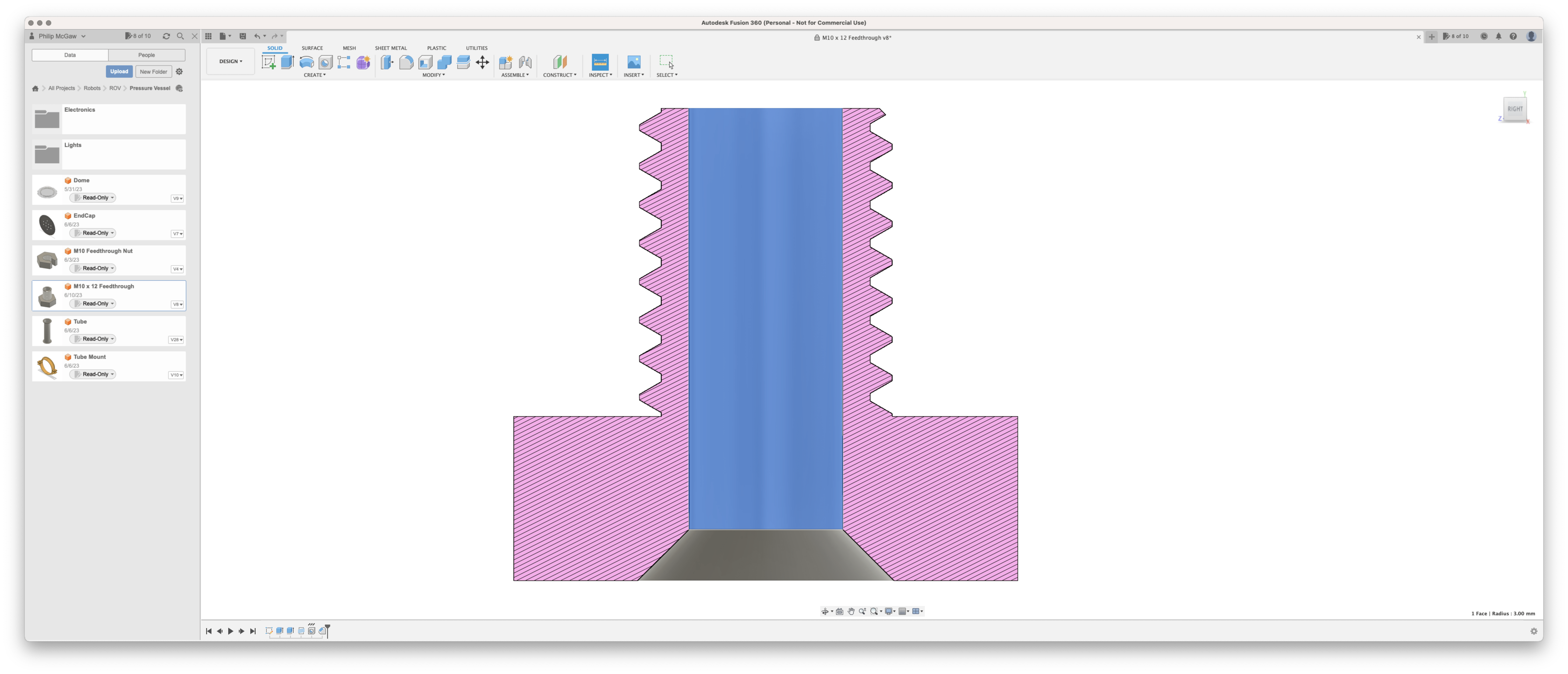
My thought is that I can take a standard M10 x 12 machine screw, and drill a 6 mm hole through the middle, and then this cavity is backfilled with epoxy once the conductors are in place.
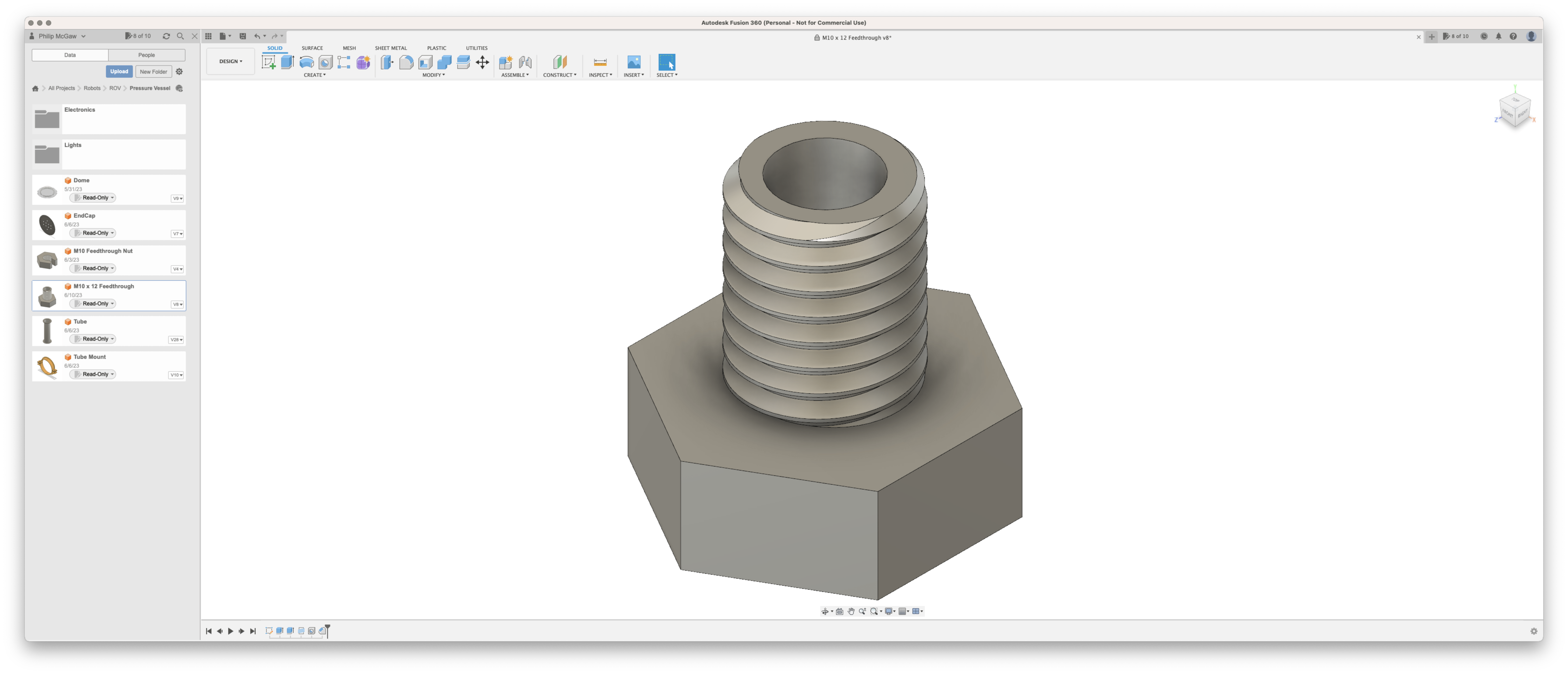
By then countersinking the hole on the head side will give an area for the epoxy to transfer the pressure too.
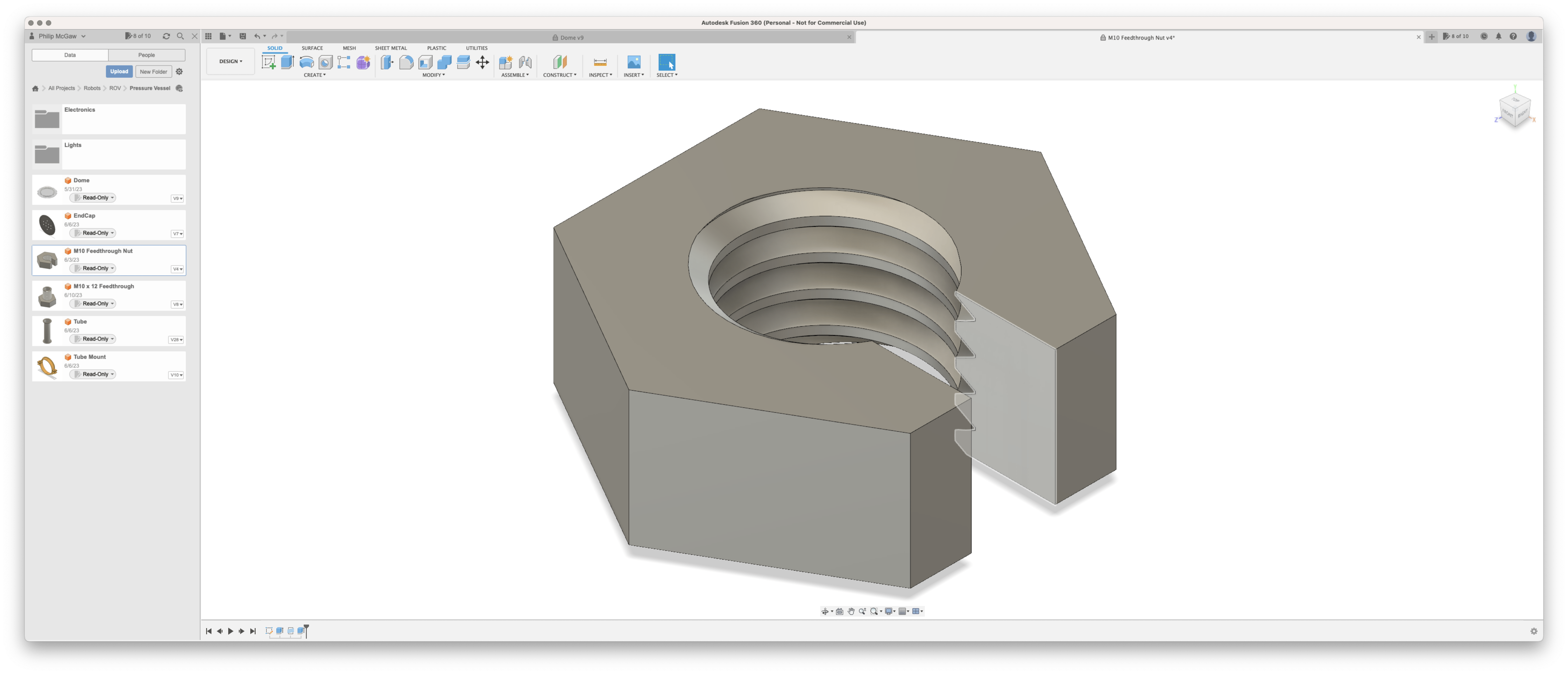
To allow the bolts to be tightened up without disrupting the cables, I am going to cut a slot in the nuts that are used to fix the machine screws to the end cap.
The following two photos show the complete assembly (without epoxy). Eight conductors have been put through the feedthrough, in these images, you can see the rubber o-ring fitted to the outside of the endcap.
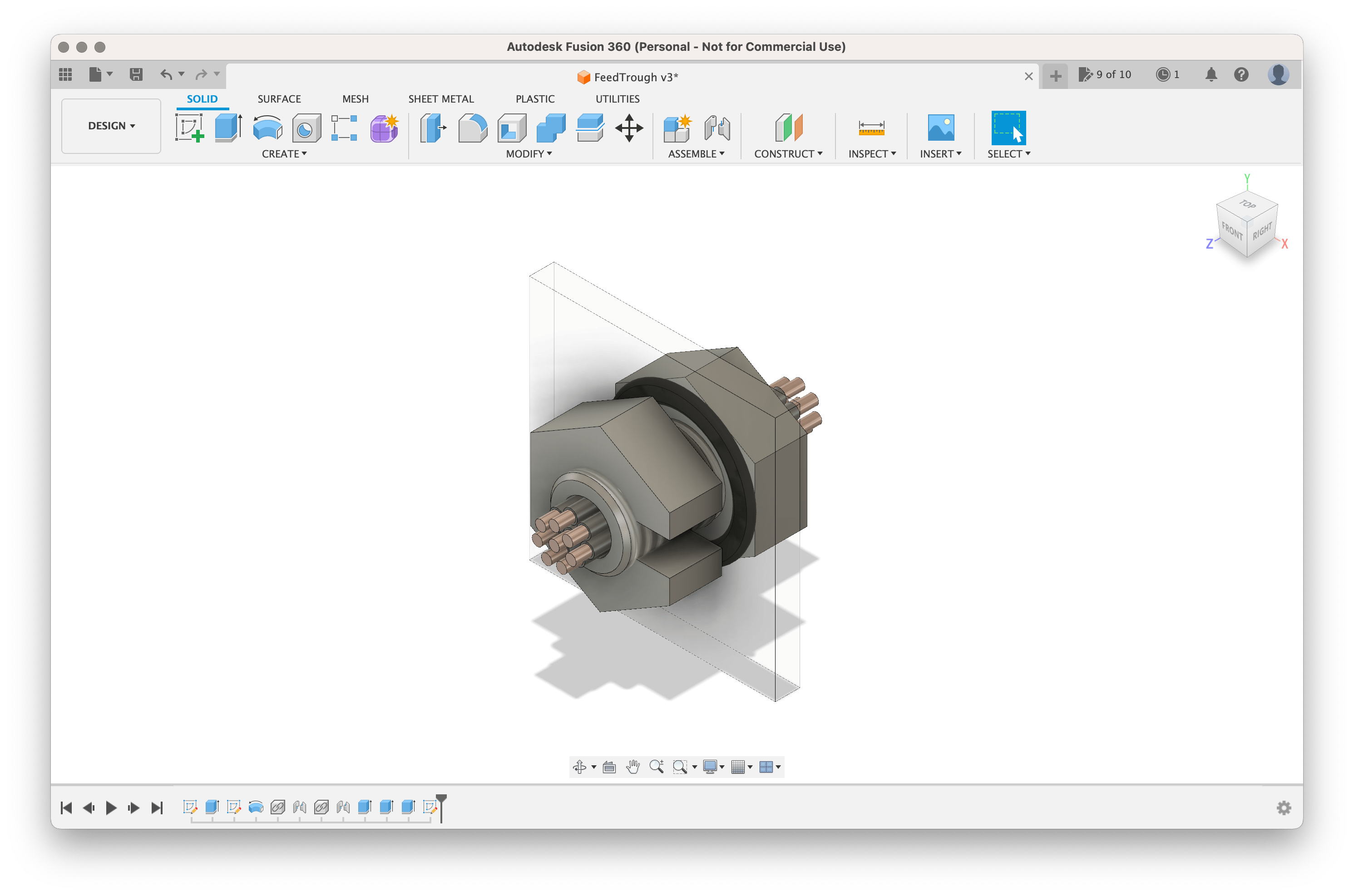
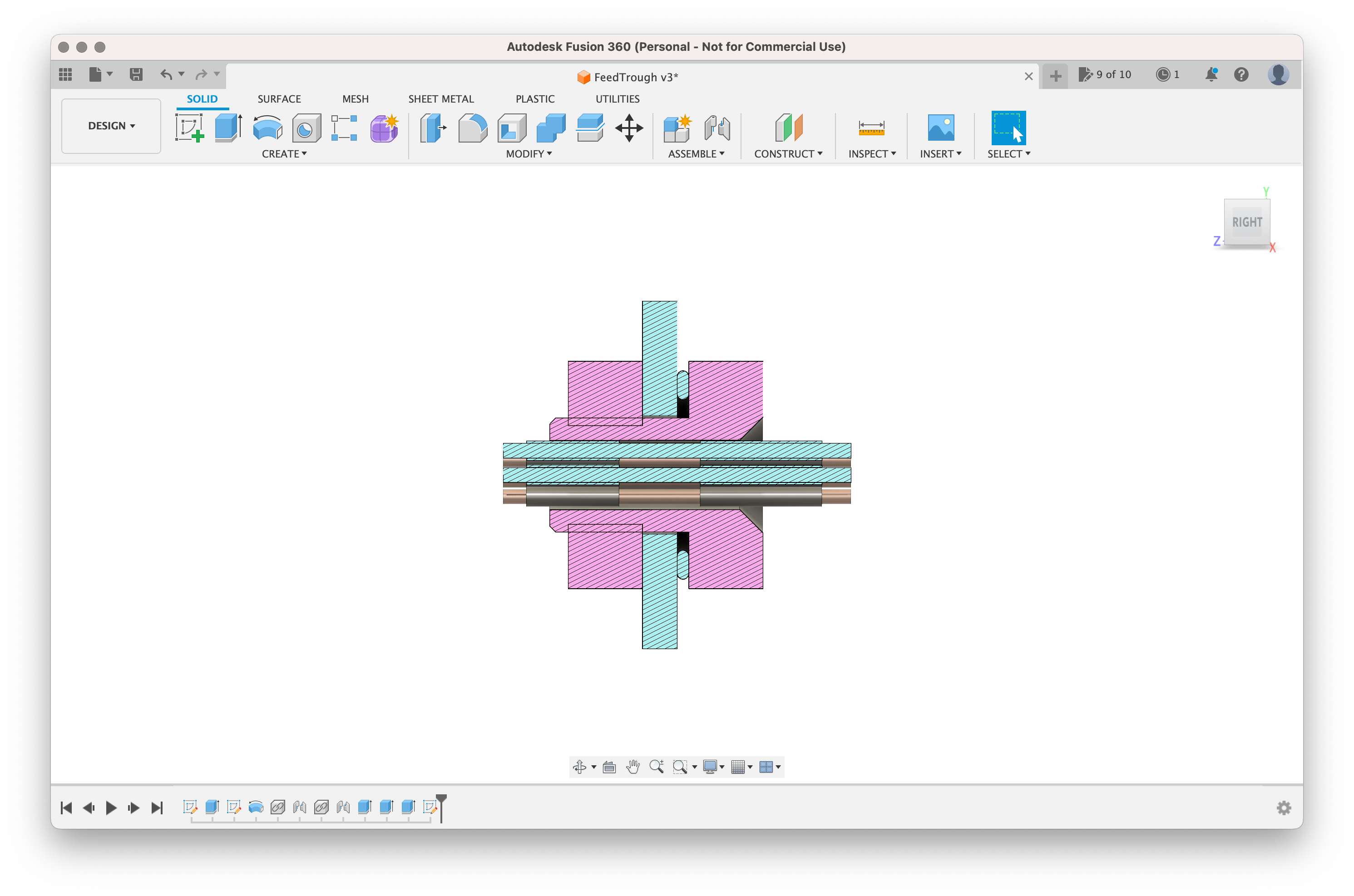
Inside the interspace, the wire is stripped of its insulation, this is to allow the epoxy to penetrate around the individual stands and prevent any water that ingresses into the insulation from using it as a path through the feedthrough.
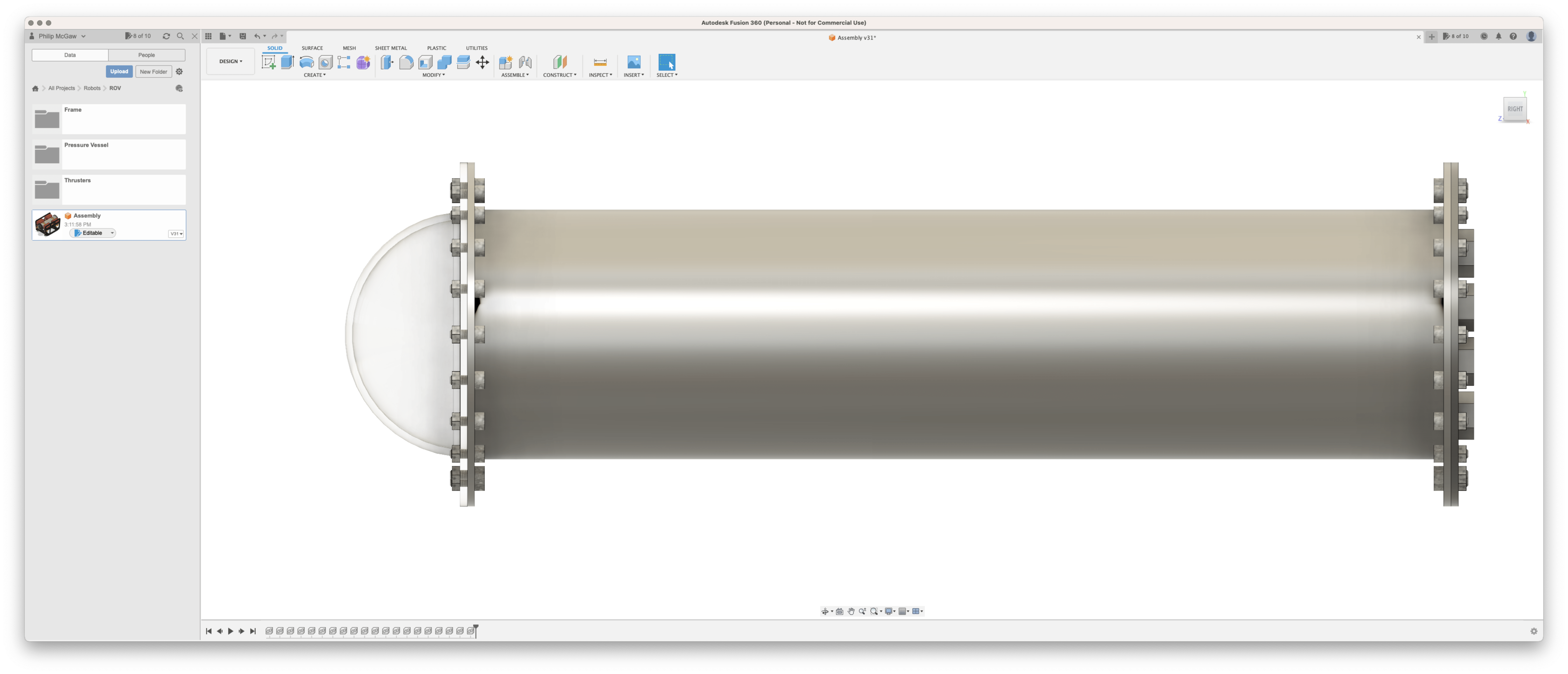
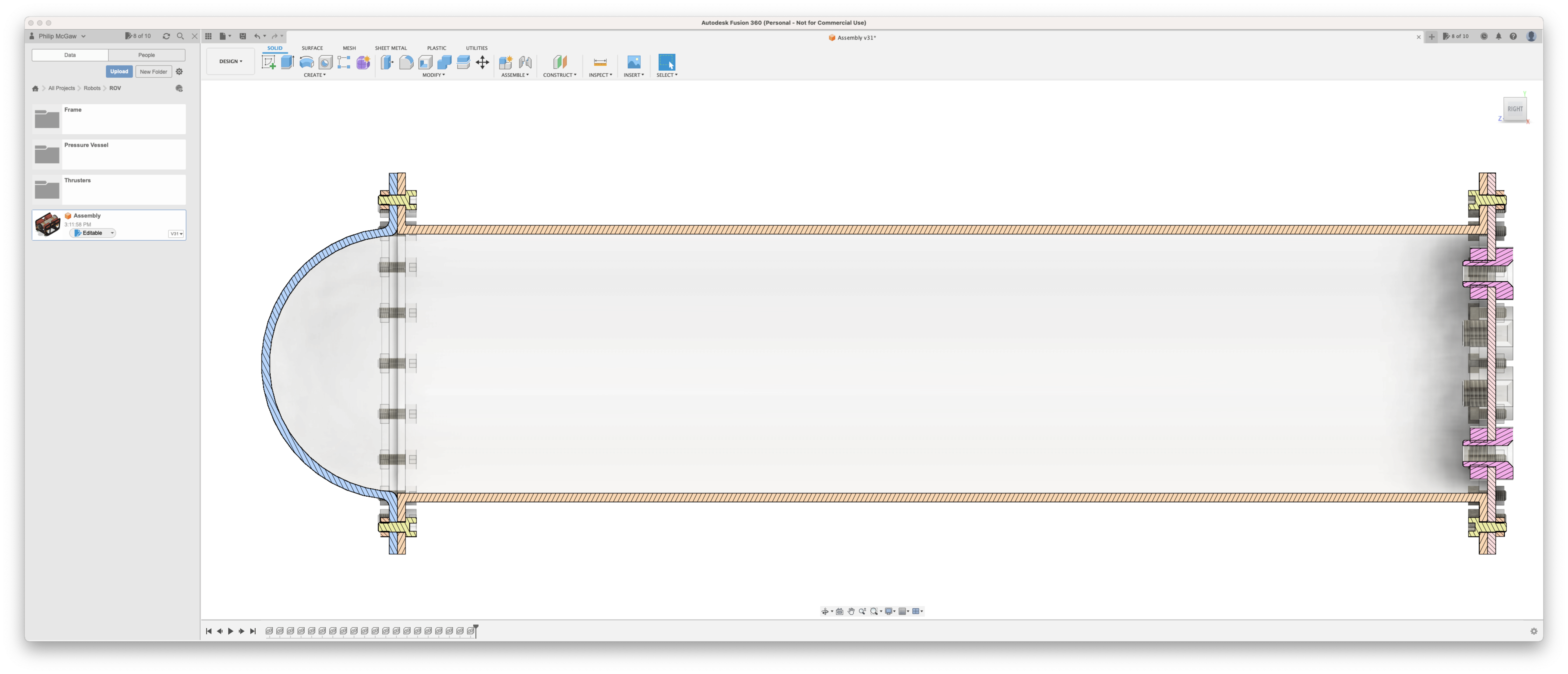
General Arrangement images

