The MCP23017 is a popular I2C 16bit IO module, it can be used to allow you to have more GPIOs available, There is also the MCP23018 available, which does fundamentally the same as the MCP23017, but with a few differences:
- open-drain outputs and higher total current-sinking capability – 400mA vs 150mA across all ports
- higher top speed on the I2C interface – 3.4MHz vs 1.7MHz
- tolerance for voltages on input pins to 5.5V (irrespective of Vdd).
On an I2C bus, each device has a unique address, typically programmable by hardware address lines. When a message is received on the I2C bus with matches the slave address, the device will respond to commands on the bus.
The slave address doesn’t change as the device is operating, so using address pins uses a lot of space for very little functionality.
The MCP23018 has only one address pin, rather than the three on the MCP23017, but still allows up to 8 devices on the bus simultaneously. Weirdly it doesn’t use the freed-up pins for anything, they just end up n/c.
The voltage presented on the ADDR pin is read at power-on and at reset and is decoded by comparing it against several threshold voltages in a 3-bit flash-ADC. This address is then remembered until the next reset.
The voltage space is divided up into 8 equal chunks from VSS to VDD, allowing for 8 of these devices on the bus, numbered 0x20 to 0x27.
The ideal voltage to present to the ADDR pin is mid-way through the range, ie. 1/16, 3/16, 5/16, … 15/16 of VDD.
Setting the MCP23018 address using a potential divider

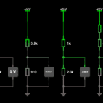
A simple potential divider can do the job of providing the address voltage, provided that the tolerance of the resistors doesn’t permit the voltage to stray outside of the permitted region. The permitted region for each address is where the ADC will definitely decode the presented voltage to the correct address, even if there is noise, drift in the reference voltages etc.
The permitted region is relatively small, less than half of the space available. The exact formula is ±20% of 1/8 of the supply voltage.
It can be quite tricky to find appropriate resistor values to set the address. If you only have two devices to attach, I suggest using addresses 0x20 and 0x27, for which any resistor will work, most modern resistors are better tolerance than 5%. but as long as you stay within a 5% tolerance you will be fine.
Resistor values for MCP23018 addressing
When generating the tables below, I have assumed 5% tolerance resistors throughout.
I have aimed for a quiesent current flow of in the order of about 1 mA when used with a VDD of 5 V. I can’t find documentation on the burden impedance of the ADDR pin, but it is probably in the order of megaohms so it won’t affect the resistor calculations.
About the table
Only the relative voltages are important, so apart from the current flow in the final column, all the voltage levels are normalised to the range 0…1. Multiply them by VDD if you want to compare them with measurements.
Picking the resistors
Look up the address, and use the R1 and R2 values from any of the tables below.
| I2C Address | Ratio of VDD (as decimal) | R1 Values | R2 Values |
|---|---|---|---|
| 0x20 | 1/16 (0.0625) | 4k7 | Open circuit |
| 0x21 | 3/16 (0.1875) | 910R | 3k9 |
| 0x22 | 5/16 (0.3125) | 1k5 | 3k3 |
| 0x23 | 7/16 (0.4375) | 2k4 | 2k4 in series with 430R |
| 0x24 | 9/16 (0.5625) | 2k4 in series with 430R | 2k4 |
| 0x25 | 11/16 (0.6875) | 3k3 | 1k5 |
| 0x26 | 13/16 (0.8125) | 3k9 | 910R |
| 0x27 | 15/16 (0.9357) | Open circuit | 4k7 |
The MCP23018 is very easy to interface with the Raspberry Pi through the I2C bus. It has 5.5V tolerant inputs, making it possible to read TTL inputs without doing any level conversion. If you want TTL level outputs, you need to level change the two I2C lines and run the device at 5V.
Adafruit produces a breakout board, that can be bought from the Pi Hut in the UK.


