For the Charging Two EVs on One EVSE project, I will need a Vehicle Inlet ‘Male’ type EV charging connector for the upstream supply from the existing EVSE. And two EVSE ‘Female’ type EV connectors to allow for connection to the downstream vehicles, Since we are in the UK I am going to use Type 2 connectors. but equally Type 1 or NACS could be used.
EV charging connectors supplier
In the UK there is a supplier called EV Connectors, whose website sells the EVSE, and Vehicle inlet connectors shown below.
These three EV connectors will be mounted into an IP 68-rated enclosure, manufactured out of either ABS or Polycarbonate, with the ancillary electronic equipment.
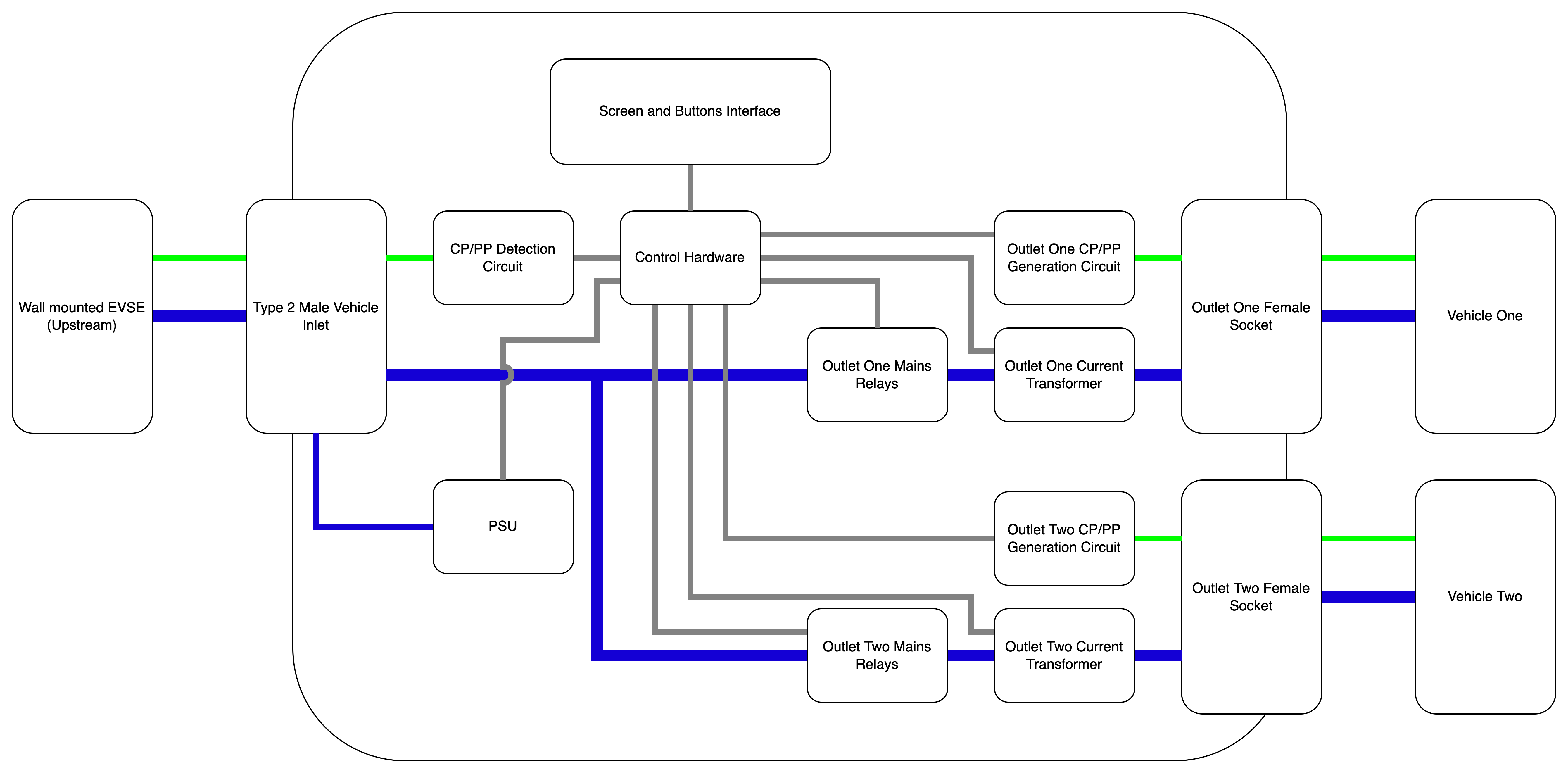
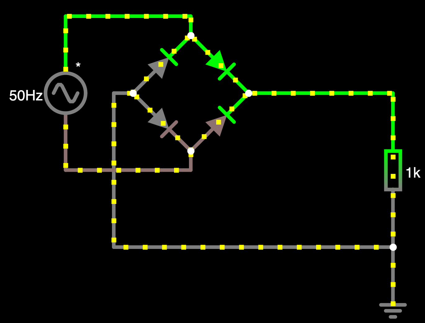
– Green is CP/PP.
– Grey is low voltage communications and signalling
– Blue is 230 VAC
The CP/PP detection circuit is required to identify the maximum current carrying capacity of the cable from the EVSE to the Type 2 male vehicle inlet, and the maximum available current from the upstream EVSE. This Passive circuitry (no micro controller is required to enable state B from State B) will also need to identify the Hydra unit as being in Charging State C (Charging non-venting) to the EVSE so that it will supply 230 VAC.
Once 230 VAC is supplied to Hydra, the internal PSU can supply 12 VDC to the rest of the control hardware, that will power up the internal microcontroller, HID (Human Interface Device), and read in the current information from the CP/PP detection circuit.
Vehicle Charging
Until a vehicle is plugged into either of the Outlet Sockets, the unit will be in a quiescent state. When the first vehicle outlet is populated, the Hydra will advertise the available current on the port to either the maximum available from the EVSE, or the maximum the downstream cable can handle, and then go through the negotion for state C and then close the outlet relays.
When a second vehicle is plugged in, the first port will have its advertised power reduced to 50% of the maximum, and then a 5 second wait until the power will be negotatated on port two also at 50% power availability.
If either vehicle’s draw is less then 50% of the availability, then using the feedback from the CTs (Current Transfomers) the advertised power on the lower draw vehicles port will be reduced, and the higher draws vehicle will be increased. This dynamic change in capacity means that should a vehicle be fully charged, the majority of the capacity can be directed to the less charged one, with the full one being limited without disconnected.
Dynamic Pricing
By using a wifi enabled microcontroller such as an ESP32, I will be able to set the maximum charge rate lower when the cost of power is higher, or via the HID disable charging completely until a threshold price is met. this will allow for the use of only cheap electricity to charge the vehicle.


