First, we are going to cover some basics in this case Resistors, but, to do this we are going to tell some lies, if you know what the lies are, then chances are that you don’t need to read this post… but please do anyway.
Resistors’ values are measured in Ohms, the symbol used is ‘Ω’ it is the SI-derived unit of electrical resistance, named after German physicist George Ohm.
The ohm is defined as an electrical resistance between two points of a conductor when a constant potential difference of one volt, applied to these points, produces in the conductor a current of one ampere,
What is Electricity?
Electricity is the flow of electrical charge
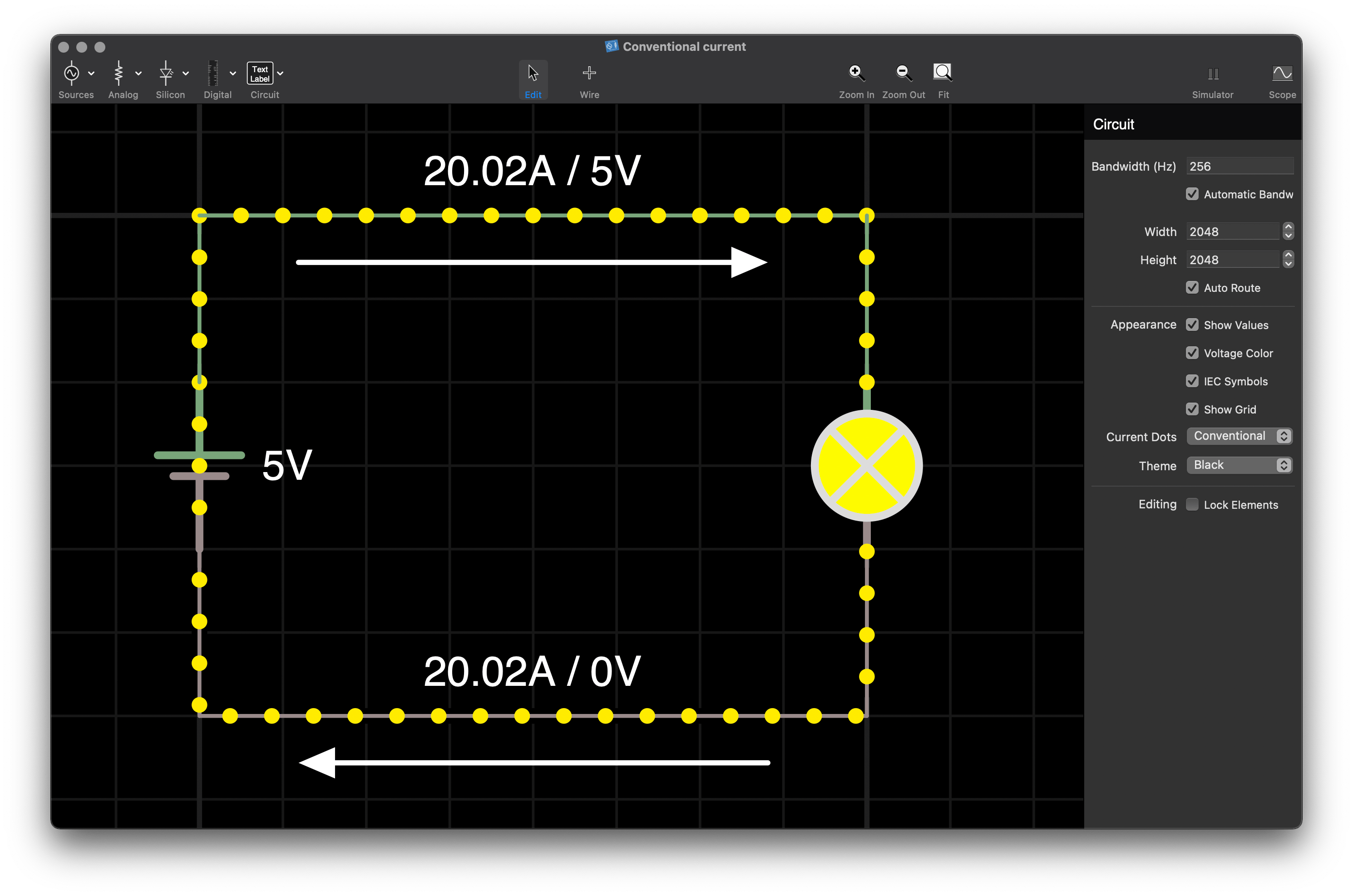
What is conventional current?
This is our first little lie;
Conventional current is the flow of a positive charge from positive to negative and is the reverse of real electron flow.
Ohm’s Law
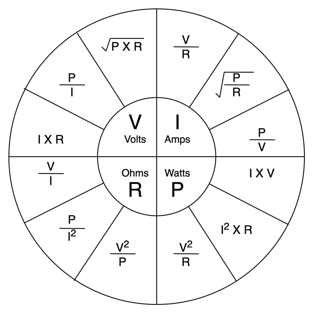
For Resistors, the main part of Ohms Law that we care about is V = I * R, (P = I * V, is no less important, however, most of the time you can work out power dissipation by the rule of thumb).
Kirchoff’s Law
- At a circuit node, the total current flowing in equals the total flowing out:
ΣIin = Σiout⇒ΣI=0 - Within a circuit mesh, the sum of all voltage drops is zero:
ΣV = 0

Examples of Resistors
- Heating element
- Light bulb
- Wiring harness (while an ideal wire should have a resistance of 0 Ω, they don’t) I will cover voltage drop at another time.
- Human body
Uses
- Resist current flow.
- Create voltage drops.
- Dissipate power.
How are Resistors sized?
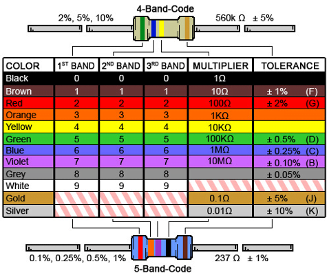
Through-hole resistors are colour coded by value, using the ‘resistor colour code’
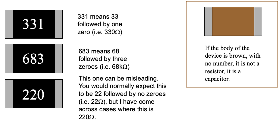
Surface mount components often have a similar arrangement to the first 3 bands, but use digits printed on the component. Beware because the rule is not always followed.
Power Dissipation

Resistors convert electrical energy to heat.
If a resistor gets too hot then there can be various failure modes depending on several factors. The resistance may change permanently. The resistor may crack and go ‘open circuit’. In some cases, a resistor can get hot enough to melt the solder, which holds it to the PCB.
Resistors change resistance with temperature:
R=R20[1+α(T-20°C)], where α: temperature coefficient, positive
Reliability of Resistors
Most frequent reasons for failure:
- thermal stress
- exceeding the maximum operating voltage
- mechanical and environmental influences
Some failure rates λ per 106 hours (Tamb=80°C, P=0.5W, Pmax=1W) According to the MIL-HDBK-217 model:
| Composite (insulated) | 0.000196 |
| Film (insulated) | 0.000206 |
| Wirewound (accurate) | 0.000134 |
Why are higher value resistors less reliable?
When using high resistances in the megaohms (and especially at 10 M ohm and more) environmental contamination such as dust, skin oils, soldering flux residue etc can easily reduce the effective resistance in unpredictable and time-varying ways.
What to consider when choosing a resistor?
Depending on where you are using the resistor, you may need to consider the characteristics of the resistors and the environment you are using them in:
- Temperature Coefficient,
- Voltage Coefficient,
- Noise,
- Frequency Response,
- Power Rating,
- Temperature Rating,
- Physical Size,
- Reliability,
- Material of construction,


31 thoughts on “Learn about Resistors”
I like to remember the V-I-R triangle for basic calculations.
V
I R
Helps me to remember that V = I*R, I = V/R, R = V/I
Oooo, thought. How about a “How this component fails?” or “Does it go bang?” section for each type of component.
Resistor: yes, it can go bang.
Capacitor: yes, it will go bang, sometimes spectacularly.
Diode: sometimes goes bang.
LED: very boring, usually fails without a bang.
…
I had planned to talk about this at a later time, as part of how to use components; I was going to use an automotive standard as a reference document.
VIR and PIV are how I remember most of this
Another marking convention I have seen for SMD devices uses R, K or M as the radix (decimal point). Examples:
10R0 = 10 ohm
100R = 100 ohm
1K00 = 1.00 kohm
10M0 = 10.0 Mohm
Yet another convention I’ve seen on both SMD resistors and capacitors is a letter followed by a digit. I and O are omitted from the letters to avoid confusion leaving 24 possible letters. Each of the 24 letters corresponds to a step in the E24 decade progression (A = 10, B = 11, C = 12, … Y = 82, Z = 91) and the digit equals the number of zeros to add.
Example: G2 is 1800 ohms or 1.8 k.
Result is in ohms for resistors, pF for capacitors.
Circuit Mesh and Circuit Node in Kerschoff’s Law section are not good terms to use. I would explain them them instead. You’re using a lot of mathematical notation – provide the English explanation next to it.
This chart is intriguing. Wish I had it when I first began studying Ohm’s Law
Is there any reason a textbook isn’t good enough for these basics? Textbooks are already peer reviewed and there are lots of validated free resources online.
There is value however in adding through your experience from building or testing something.
Excuse me if I’m coming across harsh but there are too many “educators” with their own interpretation of circuit theory, and often with errors which is no help to newcomers.
Great initiative. I like that you explain about the lie.
It may be important to mention that (and I don’t know myself) conventional flow will be used throughout the series. I’ve often wondered about transistors and should the base be taken from the + or ground?
If base is to ground, how are you getting current through the transistor?
That’s exactly why I don’t really get transistors and all that.
I’m more of a code/systems guy.
Okay, lol, I was pretty confused there for a second.
I was thinking about it all. I mean I know that V goes in through the collector and out through the emitter depending on what voltage is applied to the base.
But, and this is the thing with a bit of knowledge being a dangerous thing…
If we use conventional flow then that applies but in actuality it’s the other way…
And this is what confuses me about the whole thing.
I’ll stick with software I think
X instead of * is a bit confusing
True enough.
“x” or “X” are variables. * is an accepted function.
Do you really want “comments”? I taught electronics for 11 years.
First the ohm’s law chart is good (for DC), but I saved it till later when I could add the “time sensitive components”
If you’re going to do it all sans calculus, these are good, however, adding the calculus will change your “ohm’s law” chart considerably. That’s just a beginning.
BTW, I did teach both (for techs – algebra only, for engineers – addition of the calculus).
Let me know.
Absolutely I am after feedback and comments 🙂
I am not an educator in any meaningful way, I am an Engineer.
I know what I know, but don’t know what I don’t know. As such I am under no illusion that my knowledge is incomplete.
So any feedback that helps with making the subject easier to share is appreciated.
Lot’s of interesting info for a beginner like me. How is the wheel used?
I see others have commented upon the use of V for voltage vs. U. Perhaps I am old school, but when I first learned Ohm’s Law, voltage was represented by E. A Google search for Ohm’s Law shows a variety of Ohm’s Law wheels, but E and V seem to be the most common.
I wouldn’t consider a wiring harness as an example of a resistor. In theory it’s considered a perfect conductor. In reality there is some resistance but that’s not intentional. They also exhibit capacitance, inductance. Also I would say the that use of a resistor is to limit current as opposed to resisting current.
I have added clarification to the post, I think I will talk about equivalent series properties after I have covered Inductors.
You say the presentation is for engineering and non engineering staff, a difficult mix! One issue is the use of symbols without explanation. For example you mention ‘sum of currents’ then show a formula with the summate symbol, would non engineering staff follow that? I doubt it. Later on you show the ‘Delta’ symbol without explanation. I think a line or two explaining the shorthand formulae would help a lot.
The posts make up my notes for slides that I will present in person.
Nice work Philip! It would be great if somehow you add a real-world example at the end… like we have 120 ohms in seatbelt buckles, why it’s not a good idea to have an inline resistor in the harness etc.
Thanks for the ideas 🙂 will work on more posts.
Looks good to me.
Why are you using V instead of U? Voltage U, Current I, Resistance R, Power P if I’m not mistaken
This is a regional thing, I will add that comment to the post 🙂 thank you for reminding me.
Volts is U, not V (in my country)
I assume that you are in Germany, The Netherlands, or somewhere else in mainland Europe, and U is something related to ‘Tension’?
as Volt is an SI unit and named after Assandro Volta (1745–1827) There is a subtle difference between V and U. European notation “U” describes voltage source while “V” describes rather voltage potential. It means that U = V1 – V1 (voltage is a difference between voltage potentials
V = Voltage where I come from.