An EV emulator or EVSE test box is a device that you can use to test EVSE equipment. it allows you to change between different charge states and cable configurations. It will also allow you to draw current from EVSE equipment, as well as offering through normal valid states, An EV emulation box may allow you to introduce error states.
Commercially Available EVSE Test Boxes
There are several commercially available EVSE test boxes, I have included details of two below, but others are available, they emulate a subset of the functionality laid out in EC/EN 61851-1 and IEC/HD 60364-7-722.
Myenergi EVSE Test Box
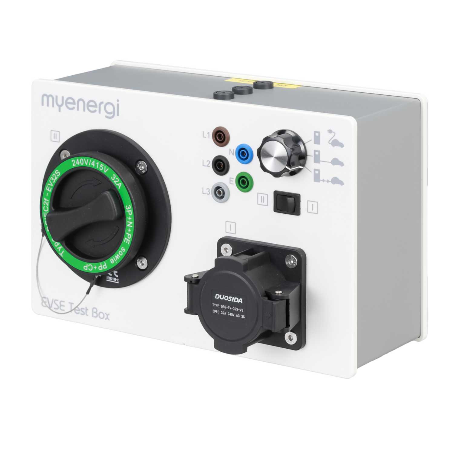
MyEnergi produces a simple EV emulator that is designed to test the Zappi as well as other AC charge point / EVSE products, it is fitted with both Type 1 and Type 2 charging sockets, and 4mm banana test sockets.
A single three-position rotary switch allows you to switch between three different charging states: Disconnected (State A), Connected (State B) and Charging (State C).
The 4mm banana test jacks enable you to attach additional test equipment to the box to perform tests such as RCD tests with test equipment such as the Metrel MI 3152.
Metrel A 1532 EVSE XA adaptor
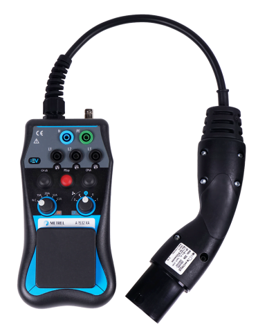
Similar to the Myenergi test box above the Metrel A 1532 EVSE XA adapter is used to connect additional test equipment to EVSE to allow for verification of electrical safety and functional testing. It is intended for testing Mode 3 EV supply equipment with a type 2 connector.
This test box supports 3-phase load testing up to 13 A and different error types, including PE open, Diode short, and CP short.
The two rotary switches allow the setting of PP Values for 13, 20, 32 and 63 A and CP settings for State A, B, and C same as the Myenergi, and an additional two settings B and D (with venting).
DIY EVSE Basic Testbox
There are three main groups of functionality that it is desirable to be able to test with an EV Emulator, Proximity Pilot, Control Pilot and RCD functionality.
Proximity Pilot Emulation
This functionality only needs to be emulated when testing EV charging case B, as the cable is not part of the EVSE equipment (case C). when the cable is not tethered it is required for both the EVSE and the Electric Vehicle to be able to determine the maximum current carrying capacity of the cable, so that the EV does not draw more current than the cable is capable of carrying.
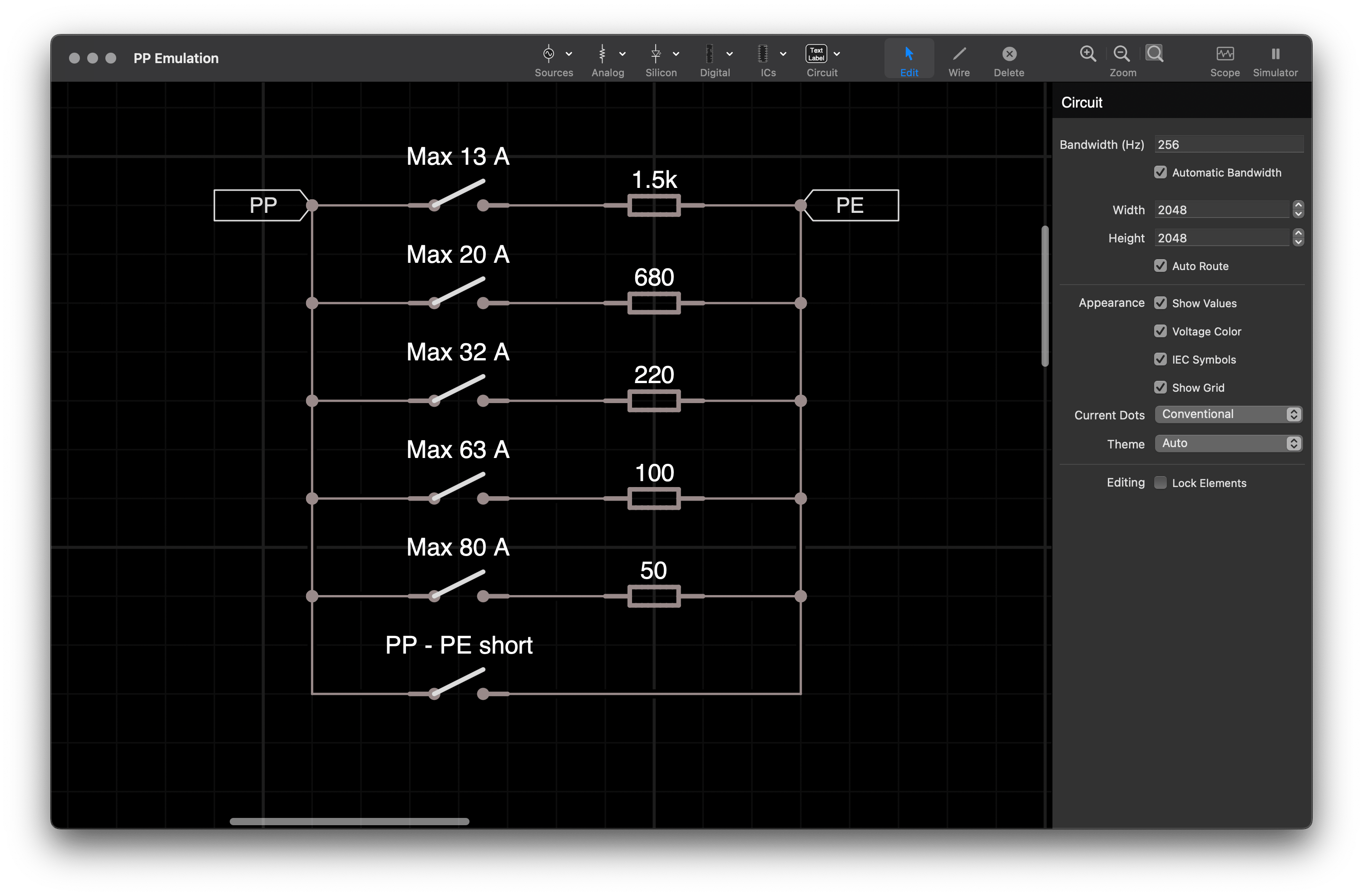
PP Emulation requires the fitting of different values of resistors between the PP line and PE (Protective Earth) at the plug end of a charging cable. This can only be achieved in charging case B.
I have drawn the circuit using discreet SPST switches, but, this would be better suited for a seven-position rotary switch, with the first position being an open circuit.
Shorting PP to PE is a fault condition, and should cause the EVSE not to supply power.
Basic Control Pilot Emulation
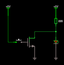
In the most basic of implementation, Control Pilot is a bidirectional communication between the EVSE and the EV which uses voltage levels to convey the vehicle state and uses the duty cycle of 1 kHz to tell the vehicle the maximum amount of power it can draw from the EVSE. The responsibility for not drawing more current than is available is on the EV.
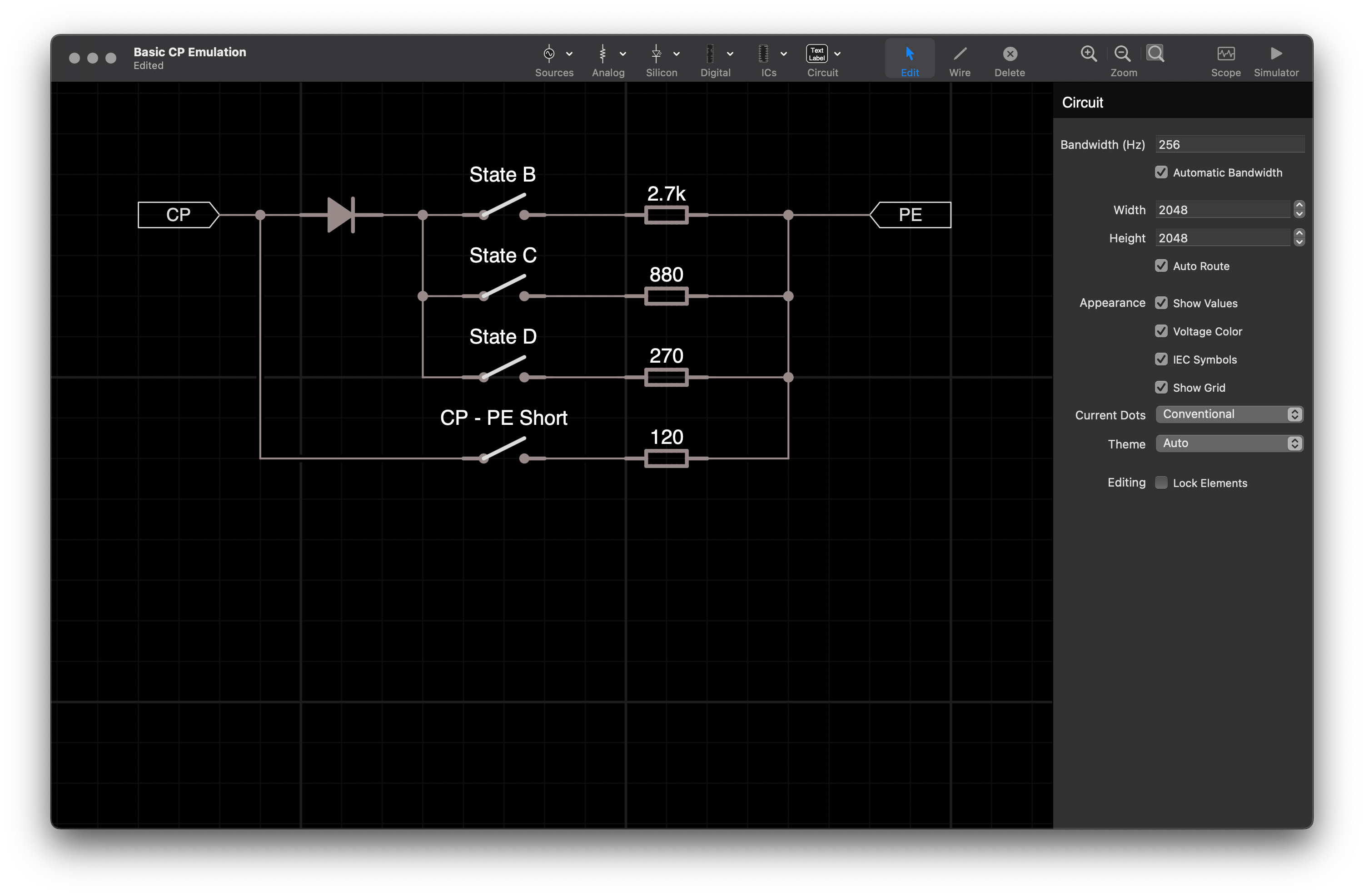
The diode used needs to be a Fast turn-off diode like the 1N4934 (Irms = 1 A, Vr > 100 V, Tr 200 ns).
RCD Test Circuit
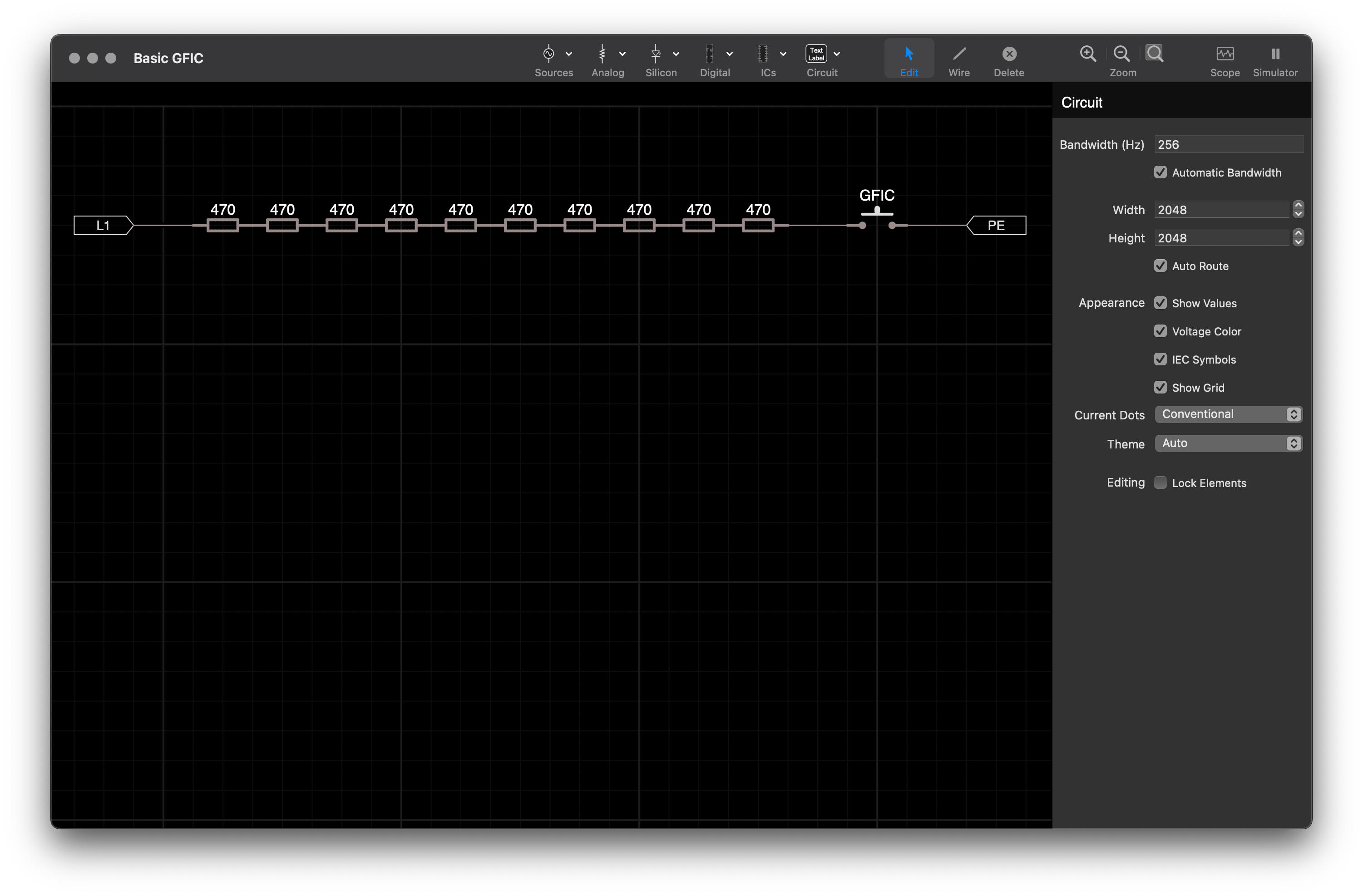
A function that is worth having is a way of testing upstream RCD (Residual Current Devices). RCDs are protective devices that isolate power if there is more than a 30 mA current discrepancy between L1 and N (isolation should occur in under 30 ms).
A way of injecting this is to use a push button switch to place 4700 Ω of resistance between Live and Protective Earth.
This functionality should be tested during the installation and commissioning of the EVSE, and the protective device is generally upstream of the EVSE on the permanent wiring of the circuit.
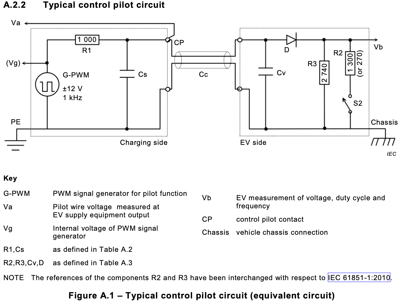
These circuits are the minimum required to enable the basic functionality of an EVSE, they do not cover the complete IEC 61851 “Example of a test simulator of the vehicle”


