Following on from my quick overview of Proximity Pilot and Control Pilot, we will need to dig a little deeper into the functionality of CP/PP to talk about how to make some circuits for a minimalist EVSE (Electric Vehicle Supply Equipment). I would not recommend using this in production as it does not implement any safety features.
We will need a power supply to implement both PP and CP and switch the mains supply to get the MVP (Minimum viable product) EVSE Charger.
Recently I wrote a post showing how to build an EV Emulator test box to allow you that allows you to load an EVSE for testing, having these circuits on hand for calibration would probably be helpful.
There will be subsequent parts to this post where I add additional functionality, and write the software to control this. I am going to design this EVSE around an ESP 32 microcontroller.
Power Supply
EVSE PSU
To take the 230 VAC supply and give us a SELV (Safety Extra Low voltage) 12 VDC supply for our electronics we will use a Switchmode PSU like the Multicomp Pro MP-LDE60-20B12, this PCB-mounted PSU takes in a wide voltage range between 85 and 264 VAC and will Output 12 VDC at 5 A (60 W).
This 12 Volt supply can power the relay coils, and all other electronics via a 5V regulator.
5V Supply
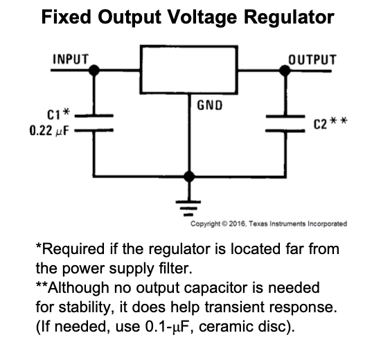
To take the 12 V SELV supply and give us 5 VDC for the microcontroller, and auxiliary equipment we can use an LM7805 12v to 5v converter. The LM7805, The LM7805 has several physical packaging options, the one we are most interested in is the TO-263 package. (For prototyping the TO-220 is easier to work with, for production SOT-223 can be used).
The LM7805 datasheet lists a peak current output of 2.4 A and can supply 1.5 A continuously, however, both of these numbers rely on suitable heatsinking and thermal management, and we don’t want to be using it to source anywhere near that much current.
The supporting components to use this component are fairly minimal, I would recommend both C1 and C2 regardless of the distance to the supply, and if you think you can get away without the output capacitor.
Control Pilot PSU
To ensure compliance with the IEC61851 / J1772 EVSE Interface standard we need a duel rail power supply, +12 VDC, and -12 VDC, we can use a 1-Watt Meanwell unregulated DC-DC converter such as the DPU01L-12,
According to the datasheet, the output of the DPU01L-12 has an accuracy of ± 3% with a maximum output capacitance of 100 μF for each output, we will need to load the output slightly to give stability as well as offer decoupling for the rest of the circuit—the IEC standard calls for a voltage tolerance of ±5%.
Under full output load conditions, the DUP01L-12 sinks up to 255 mA from the 5V supply and can supply up to about 42 mA on each of the ±12 VDC rails.
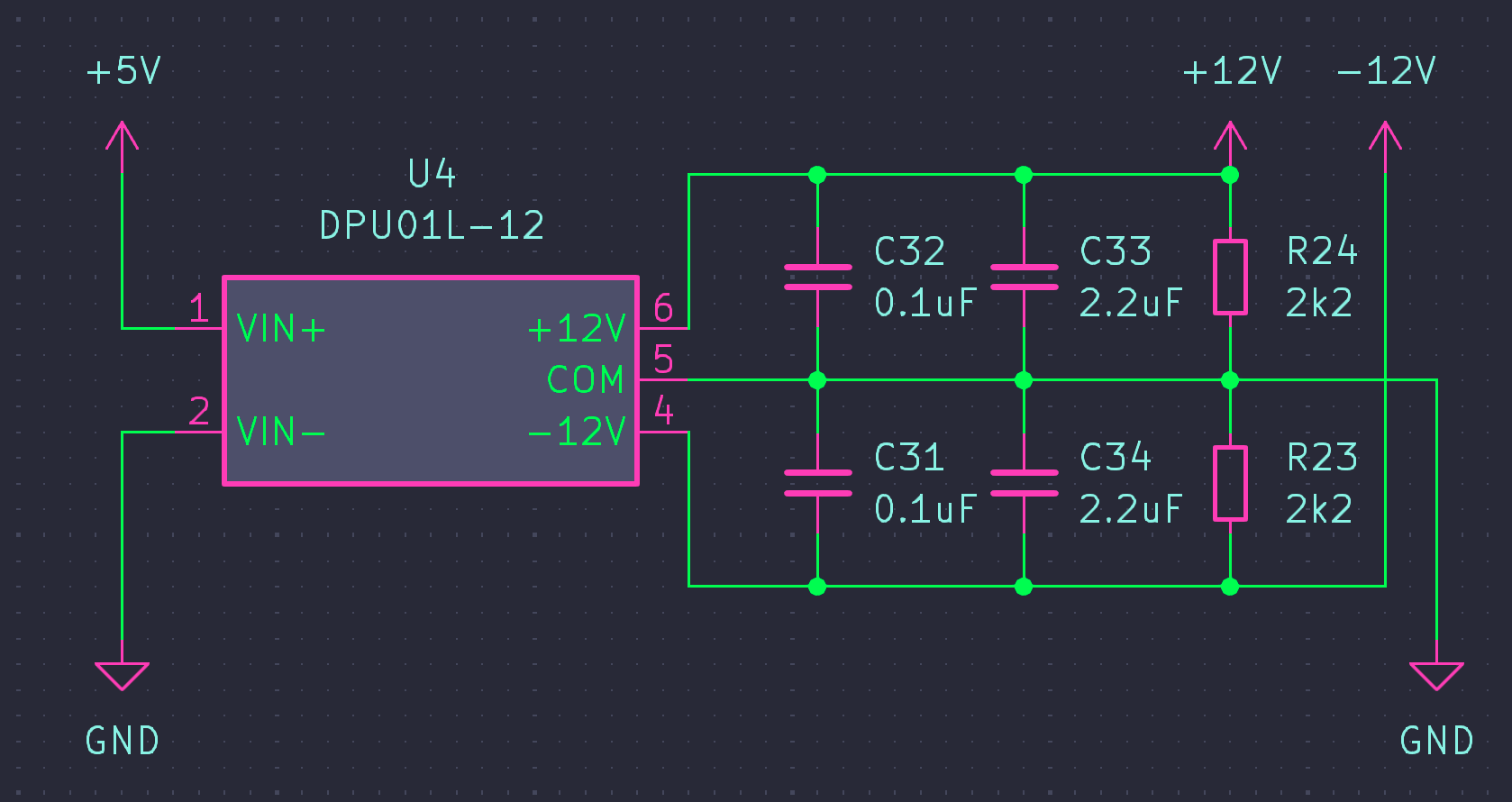
We could use the Meanwell DPU01M-12 rather than the DPU01L-12, the M part number uses a +12 VDC supply to generate the ± 12 VDC.
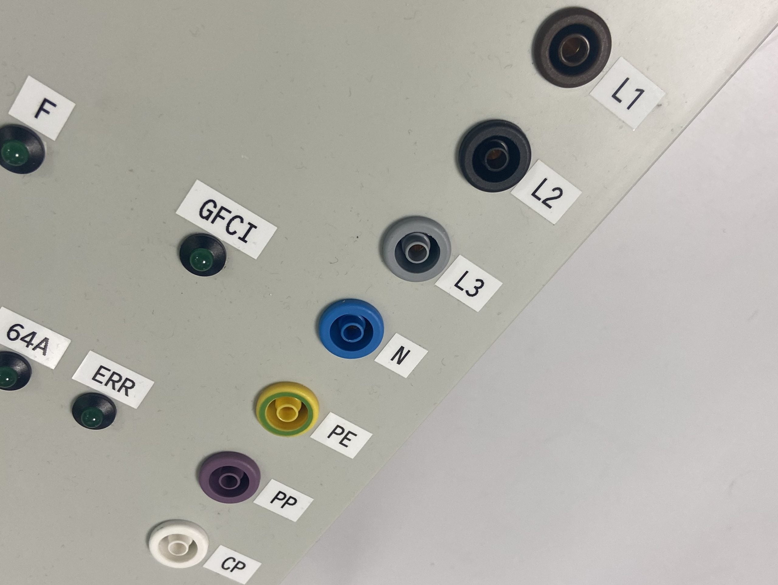
Proximity Pilot Circuit
When a tethered cable is attached, the maximum current advertised by the EVSE should naturally not exceed the maximum capability of the charging cable. In this case, the maximum current is hard-coded, and the PP line is normally not connected back to the EVSE electronics.
However, when an EVSE accepts detachable cables, it must first determine the maximum current carrying capacity of the cable. This is done via a resistor mounted in the plug between the Proximity Pilot, (PP, sometimes called Plug Present) and PE (Protective Earth) of the detachable cable. (IEC states removable cables should have no release buttons). Both ends of the cable should have the same resistor value so both the EVSE and vehicle can determine maximum current capacity.
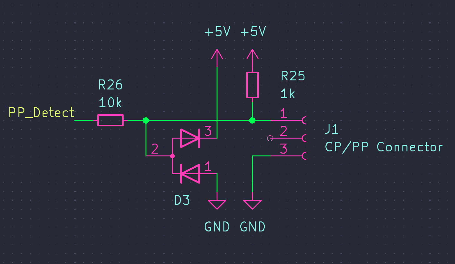
The PP analogue output is used to determine the maximum current carrying capability of the detachable cable. This resistor acts as a simple voltage divider with R25.
| Resistor fitted to charging cable (Ohms) | Amps (Cable) | PP_Detect Output (Volts) |
|---|---|---|
| 1500 | 13 | 3 V |
| 680 | 20 | 2.024 V |
| 220 | 32 | 901 mV |
| 100 | 63 | 454 mV |
| 50 | 80 | 238 mV |
Control Pilot Signal Circuit
The Control Pilot signal is based around a ±12 square wave, with a frequency of 1 kHz ± 0.5%, the mark space ratio varies depending on the current available for the EV. Feedback from the EV to the EVSE is managed by manipulation of the magnitude of the waveform.
The waveform with its mark space ratio is generated externally, via the microcontroller that will drive the EVSE, this is outside the scope of this post, but, will be addressed in the next one.
To make a ±12 V square wave, we will take a 0-5 VDC signal in, and using an operational amplifier we will build a comparator using an operational amplifier. I have modelled the circuit in iCircuit below, this is an indicative simulation and makes assumptions about the components (green trace is the 1kHz input signal, yellow trace is the output of the comparator).
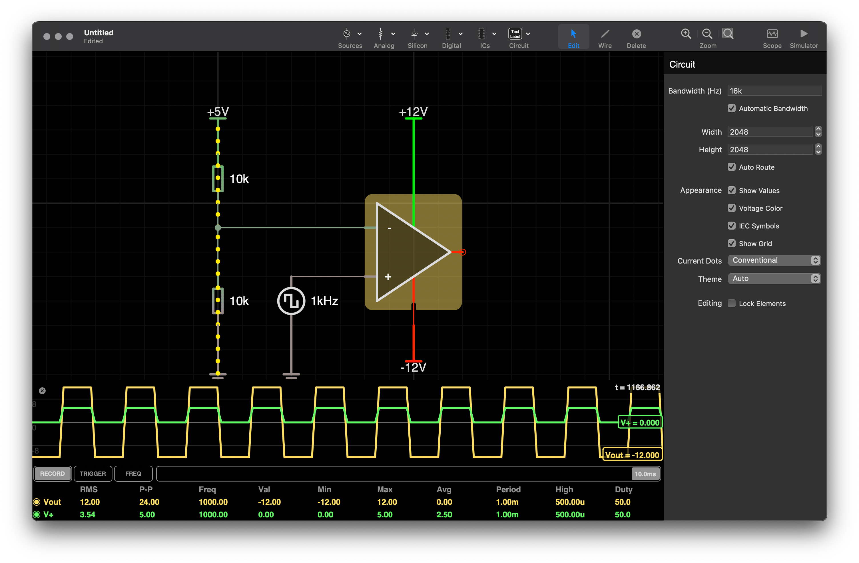
The op-amp (operation amplifier) we will use is an LM7332 will convert this to a ±12 V signal and drive the control pilot via a 1K series resistor. The LM7332 is a duel rail-to-rail op-amp meaning with ±12 V supply rails you can get the full ±12 V output on each of the two op-amps in the package.
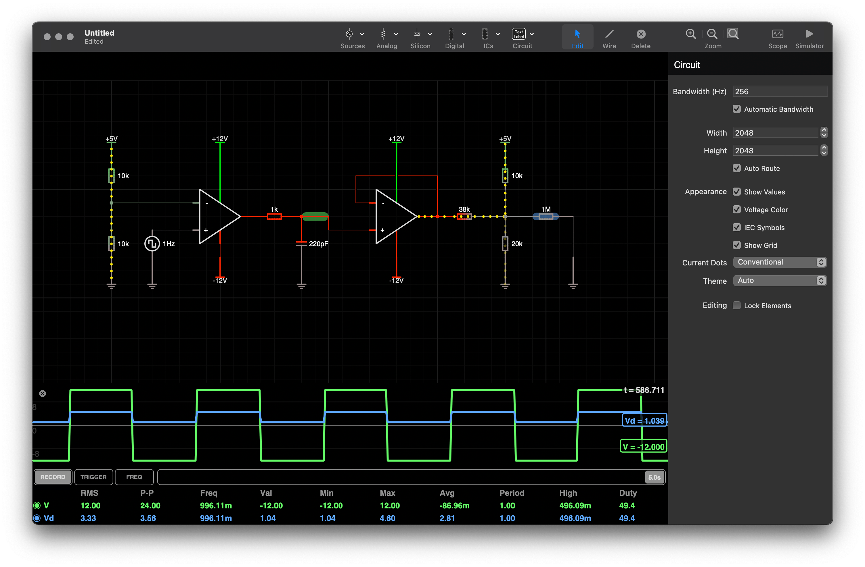
A 1 MΩ resistor has been used to represent the analogue in pin on a microcontroller, or where a voltmeter would be applied. The ATmega328P datasheet claims an input impedance of 100 MΩ.
Loading the Control Pilot signal circuit
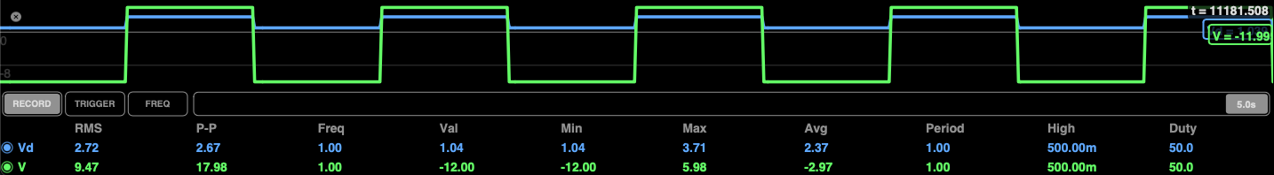
I have added the representative CP EV test box circuit to the midpoint of the EVSE circuit, so we can see the values of the Vd signal change as different states are applied.
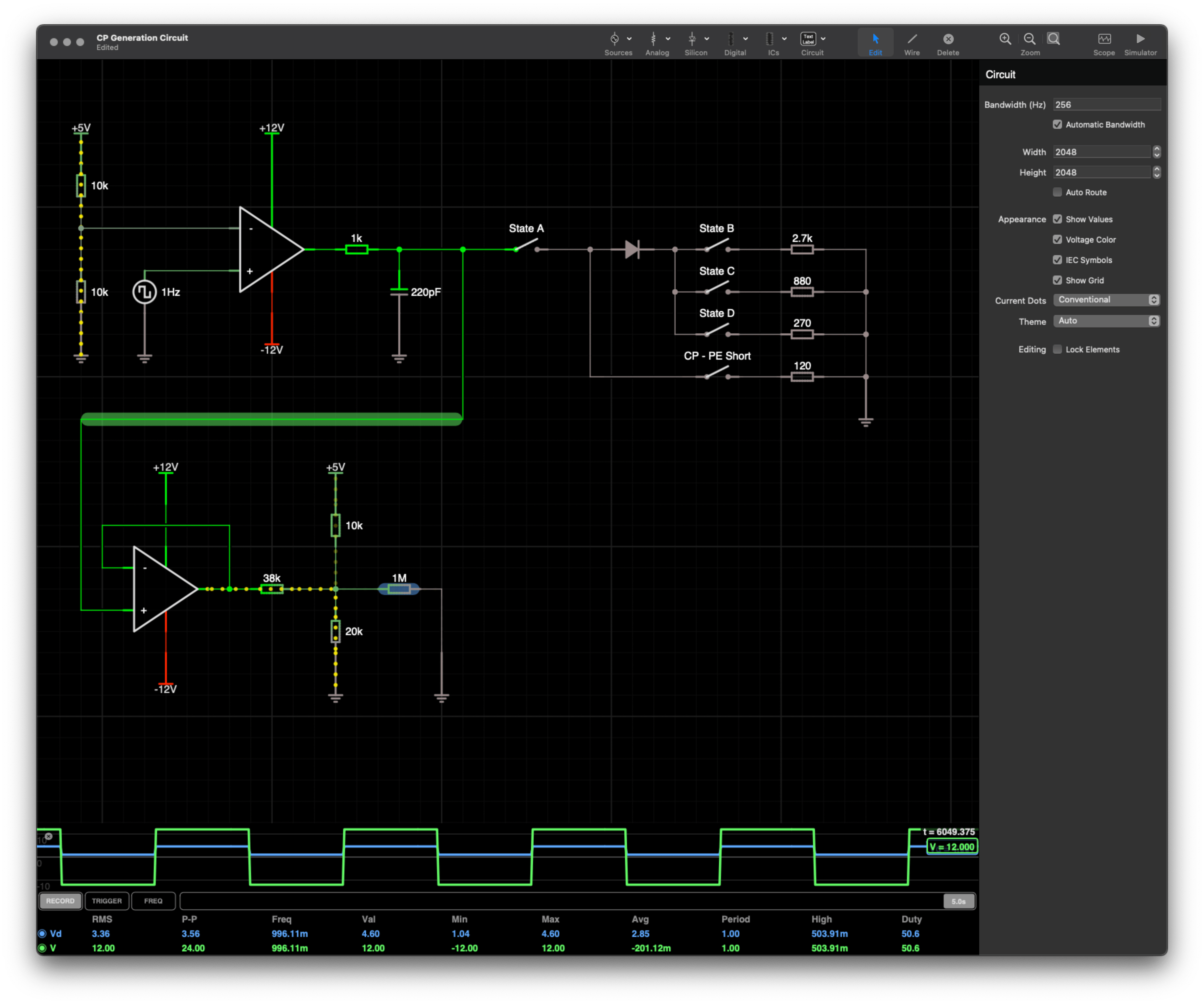
Closing the switch marked “State A” applies the square wave to the EV Simulator box, but makes no change to either signal level.
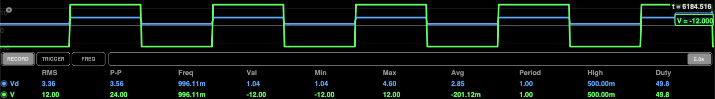
Closing the switch marked “State B” in addition to the “State A” switch changes the maximum voltage from 4.6 V to 4.15 V
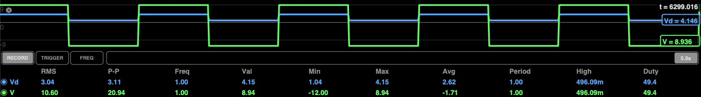
Opening “State B” and closing “State C” causes this voltage to drop to 3.71 V
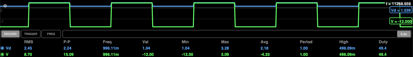
Opening “State C” and closing “State D” causes the voltage to drop to 3.09 V
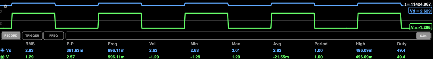
If the CP – PE and the State A switch are both closed, then we get a maximum voltage of 3.01 V which is not a valid value.
I will write a subsequent post with further details on these voltage levels and charging states when it comes to talking about putting this all together into a box, and write some software to control this all.


