I still need B to give me more design hints beyond “Tank Tracks” for the PiWars robot design. However, I have been making progress with the design of the Traction System.
A company called Vex Robotics sells a kit of parts to make up tank treads. The kit includes about 1.5 meters of tank tread links, four drive sprockets, four double bogey road wheels, two tensioner idlers and fixing hardware. The drive sprockets can also be used as idler wheels. The mounting hole for the sprockets is a square 0.125″ (on a side). Vex Robotics sell 1/8″ axle rod in various lengths.
One of the comments on my Drill motor post was from Max Allan, who commented: “My guess is that the driveshaft will get shredded/snap. I’d suggest making a square hole down the middle and put a length of bar down it.”
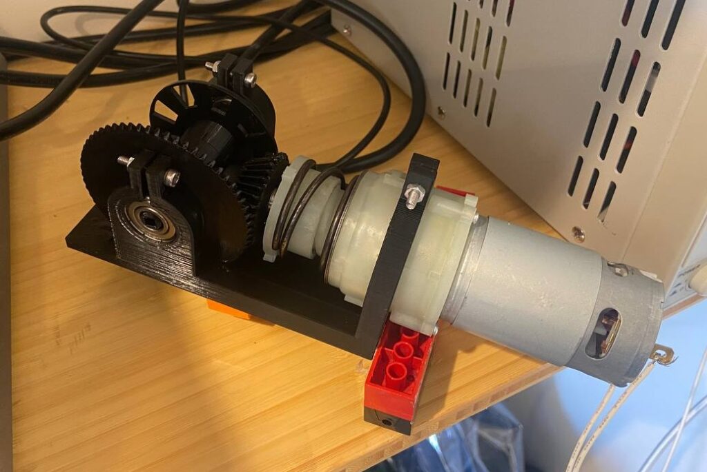
Since that post I have re-designed the gearbox, going from 17:37 teeth to 31:61which approximately doubles the number of teeth and keeps the ratio about the same. Both 90° bevel gears have a prime number of teeth.
Also included in the redesign is a simplification of the drive shaft design, from four printed parts to two plus the 1/8″ rod. I imported the drive sprocket step file from Vex Robotics into Autodesk Fusion 360 to allow me to model this setup.

This redesign simplifies the assembly and reduces failure points in the Traction System, while the insertion of the axle will allow for more force to be transmitted to the drive sprocket.
The Traction Control system still uses a feedback ring, this ring will pass between an IR LED and IR photodiode, and give the ESC (Electronic Speed Controller) feedback on the number of rotations of the output shaft, this system is still being designed, I will post about it in more detail.


9 thoughts on “PiWars Robot Traction System”
Very cool. Was my chosen career but they wanted prerequires or w/e. Lol
Electromechanical engineering paired with 3d printing sounds like a blast.
Very cool
Nice legos
Nice project! Thanks for sharing the details!
My two cents: learn micropython. It’s not the best language but it is the fastest for prototyping and the most “3rd part supported” by which I mean, there are TONs of project examples fully open sourced and ready for stealing! You won’t regret it!
Mason Harwell Thank you, and along with with sean’s suggestion I will re-visit the Pico and Micropython.
Nice, have you thought about placing the gear teeth on an angle so that they have a more secure contact area?
I have thought about using helical bevel gears (spiral bevel gears), but for the increased complexity of drawing them, there is very little advantage.
Helical gears have the advantage of the mechanical loading being over more than just the single tooth in contact, which helps reduce indervidual loading, and backlash.
The gears are massively over-engineered for the amount of torque that is going through them at the moment, and Backlash is not a massive concern.
If I wanted the input axis and output axis to be offset, I could consider Hypoid gears… one advantage of that is that I could move the motor to be lower in relation to the output shaft, reducing the center of gravity.
One of the disadvantages of Hypoid gears is that there is a sliding motion between teeth, causing additional wear, this may be fine for well-lubricated smooth metal on metal gears, however, 3D printed surfaces tend not to be smooth.
That is pretty cool I like gears. 🙂
You might just as well use the arduino ide, and C/C++ with the RP2040. https://www.upesy.com/blogs/tutorials/install-raspberry-pi-pico-on-arduino-ide-software
Thanks for that link, I will have a look at it shortly