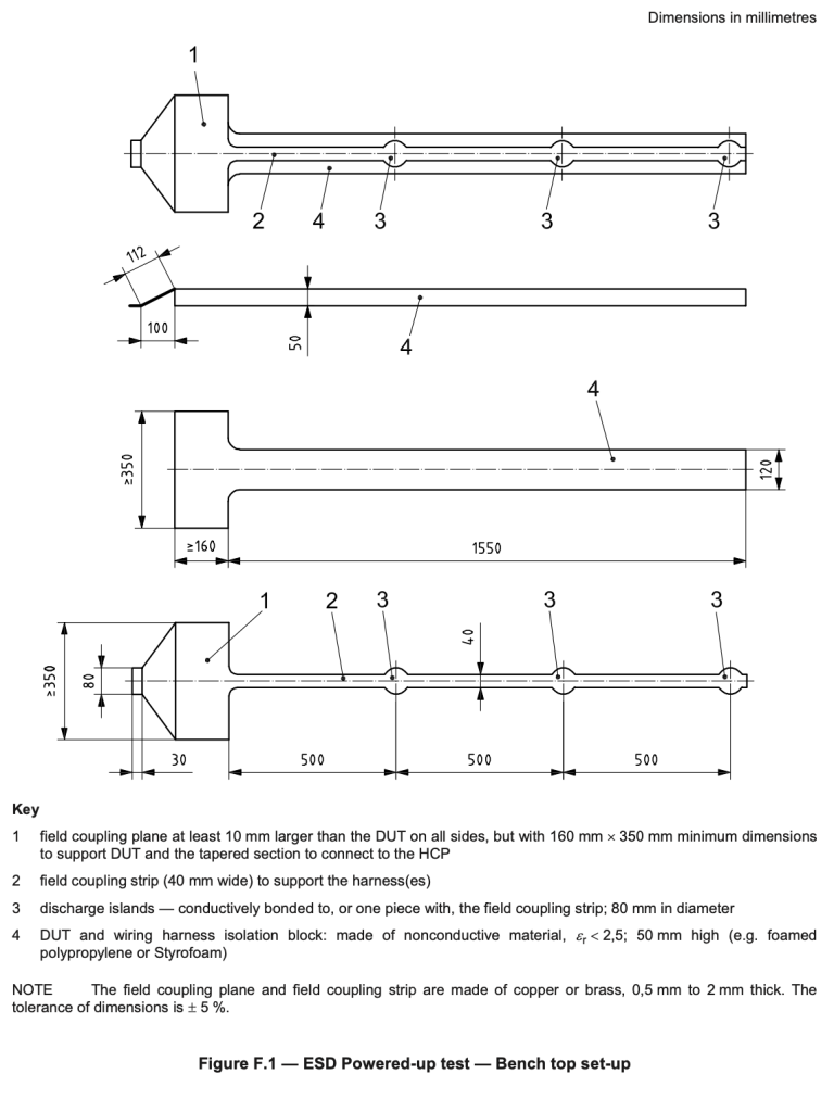
When I was working for ARRIVAL, setting up the Automotive EMC lab there, I needed an ISO 10605 Annex F island as part of the ESD test setup. This test setup is as far as I am aware unique to Automotive, and as such commercial EMC Technicians and Engineers are unlikely to have experienced this ESD setup. I will follow this article shortly with my ESD blog post, which will refer to it, and expand on the use of this peculiar arrangement.
ISO 10605:2008, “Road Vehicle — Test methods for electrical disruptions from electrostatic discharge” and the Amendment from 2014 have the same requirements in Annex F for the field coupling (or Island) Jig for ESD testing.
ISO 10605 Annex F Island test setup
The test setup for using the field coupling jig is also defined in Annex F, under Figure F.2 – Test set-up – Application of direct discharge and Figure F.3 – Test set-up – Application of indirect discharges, I have included them in this post as background reading for the next post I write about ESD testing.


As you can see from the above test setup diagrams, and the details for the jig manufacturing, this is not something that you will use outside of the Automotive domain.
The entire test island jig is placed 50 mm above the (Horizontal Coupling Plane) on an isolation block made of a non-conductive material such as polypropylene or styrofoam with a relative dielectric constant (εᵣ) of < 2.5.


