In my past two posts, Storing When an Arduino Sketch was Compiled and Arduino Serial Number we covered how to know the Compiled date, Firmware version number and Serial number of a bit of test equipment, in this post, we will encode the Hardware Revision number, so that we know what the revision of the main PCB is.
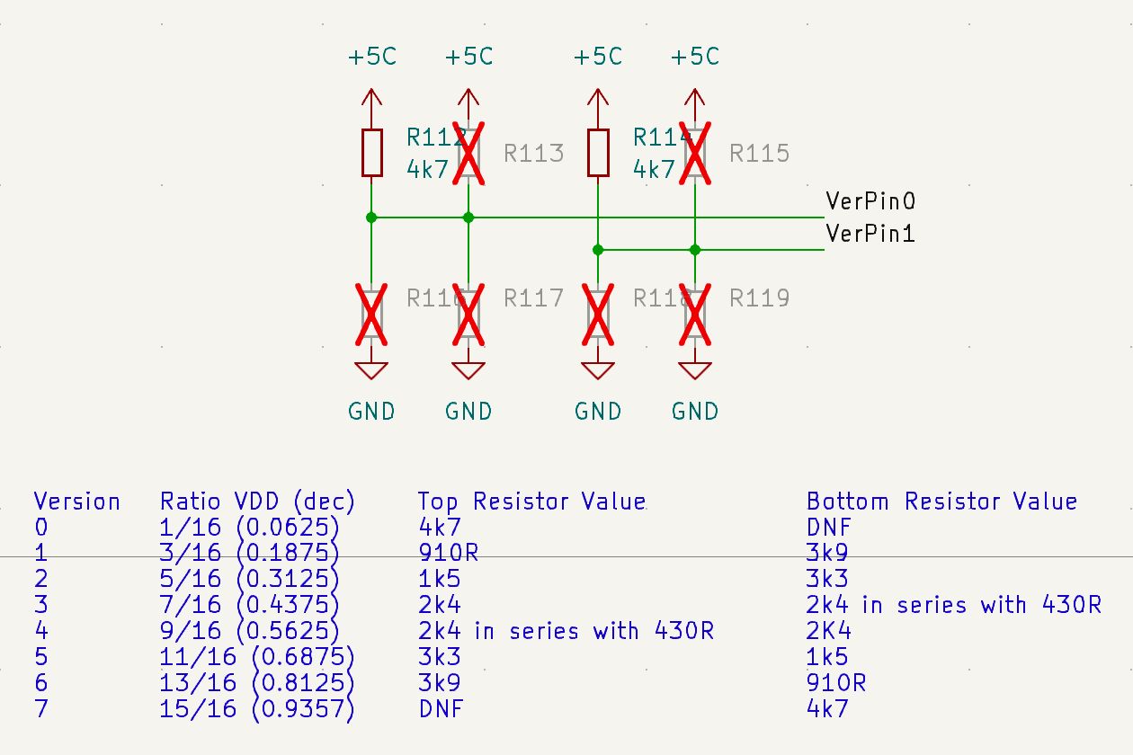
The revision information is encoded using two resistor dividers, each of which can encode eight states.
The two dividers, each have four resistors, as for values three and four you need to put two resistors to get the right ratio.
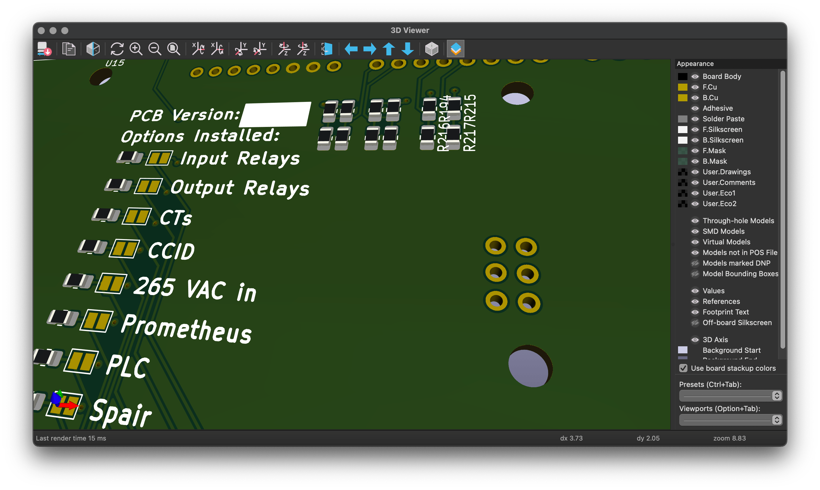
As you can see in the schematics below, and the PCB render to the right, all the pads are laid out at the beginning, even though they are marked as DNF (Do Not Fit). Also in the image you can see that optional population-level jumpers are fitted, so the final test equipment can have different population levels but use common firmware and hardware.
The values have been chosen to minimise the quiescent vampiric current draw of the dividers. the net +5C is being used as the supply rail for the hardware version resistors, and the population level resistors. This is the same supply used to power up the microcontroller and is un-switched, separate from the supply of 5V equipment in the device.
Resistor Values
| Value | Ratio of VDD (dec) | Top Resistor Value | Bottom Resistor Value |
|---|---|---|---|
| 0 | 1/16 (0.0625) | 4k7 | DNF |
| 1 | 3/16 (0.1875) | 910Ω | 3k9 |
| 2 | 5/16 (0.3125) | 1k5 | 3k3 |
| 3 | 7/16 (0.4375) | 2k4 | 2k4 + 430Ω |
| 4 | 9/16 (0.5625) | 2k4 + 430Ω | 2k4 |
| 5 | 11/16 (0.6875) | 3k3 | 1k5 |
| 6 | 13/16 (0.8125) | 3k9 | 910Ω |
| 7 | 15/16 (0.9357) | DNF | 4k7 |
Falstad Simulation
You can open and close the switches in the following simulation to change the voltage across the voltmeter.
powered by Advanced iFrame. Get the Pro version on CodeCanyon.
Arduino Code for Version Numbers
VerPin0 and VerPin1 are taken to Pin_A0 and Pin_A1 on the Arduino, and the code for reading it in is as follows
  int valA = analogRead(PIN_A0);  // Analog pin A1
  int valB = analogRead(PIN_A1);  // Analog  pin A0
  valA = map(valA, 0, 1023, 7, 0); // Maps the value from analouge pin to 0-7.
  valB = map(valB, 0, 1023, 7, 0);

  if (valB != 0)
    valB = valB + 7;          // adds 7 to the MSB if it is not zero
  Hardware_Rev = valA + valB; // gives us a hardware version between 0 and 15.
This code is added to the version() function mentioned in the previous post.
Simulation of Version Numbers (Wokwi)
There is a known issue with the simulation in Wokwi, where potential dividers don’t produce the right output, so this simulation won’t work as well as it should, but if you build it in hardware it should work as required.
The below simulation can be opened full screen in Wokwi.
powered by Advanced iFrame. Get the Pro version on CodeCanyon.
In the future
Now we have encoded the Firmware, Serial number and Hardware Version Numbers in a way that is accessible to the microcontroller, we can use these values to lock specific firmware versions to only work on pre-defined hardware versions.
For test equipment I have made before, I have used SCPI (Standard Commands for Programmable Instruments) to talk to the hardware, in a future post I will talk about how to use the microcontroller.


