The main communications between Level 1 and 2 EVSE (Modes 2 and 3 and sometimes 4) and Electric Vehicles is via the Proximity Pilot and Control Pilot lines on the connectors.
Level 1 (Mode 2) is portable charging equipment like an “In Cable Control Box” (ICCB) (commonly referred to as a “Granny Charger” or “Granny Cable”) whereas Level 2 (Mode 3) is installed charging equipment.
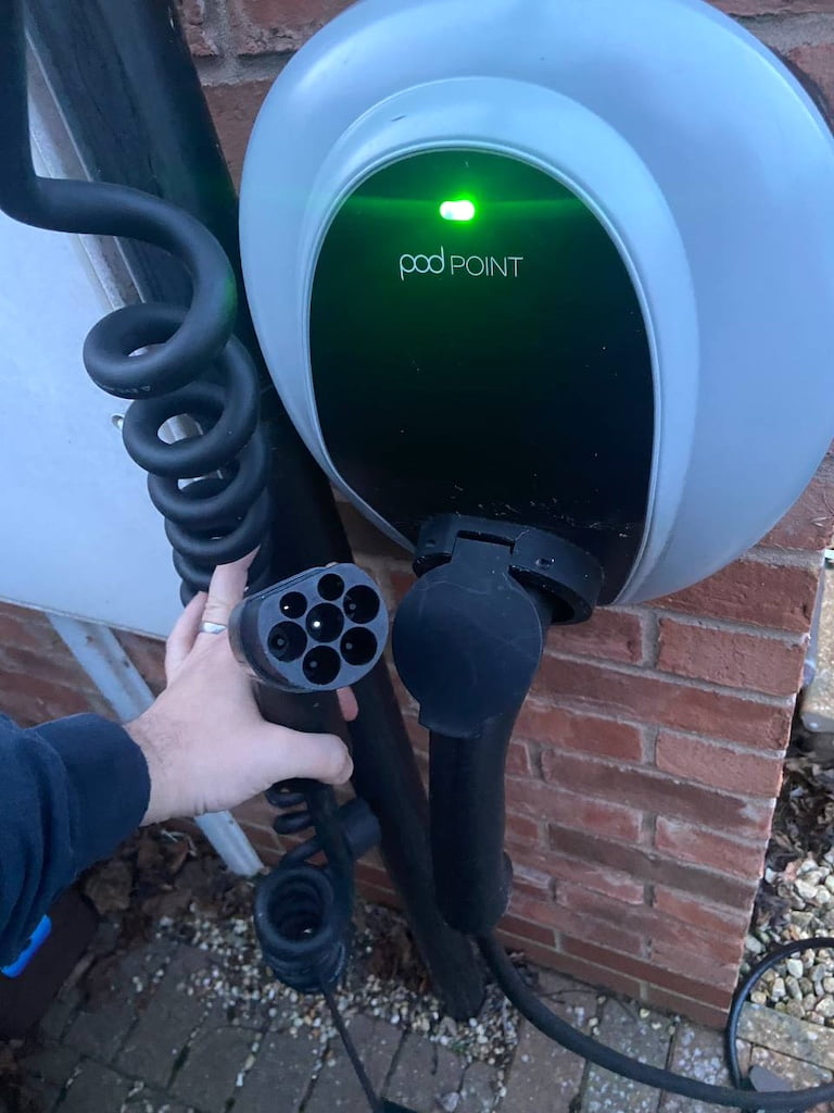
Proximity Pilot and Control Pilot signals are used to communicate between the EVSE and the EV / PHEV, these two low-voltage signals are referenced against the protective earth, on the left you can see our PodPoint 3 Solo EVSE, I am holding the GB/T end of my Type 1 cable. The connector on the front of a connecterised EVSE is a GB/T port regardless of the connector on the other end of the cable. (we have both a Type 1 and Type 2 cable as we have two Nissan Leafs).
The two small cavities at the top of the connector are the PP (Proximity Pilot) and the CP (Control Pilot) pins, with the larger centre pin being the safety earth return pin.
The high-level specification and functionality of the CP / PP signal are defined in BS EN IEC 61851-1:2019 (IEC 61851-1:2017) “Electric Vehicle Conductive Charging System. Part 1: General Requirments” (This ensures compliance with SAE J1772).
Clause 3.3.3 defines the Control pilot function as a “function used to monitor and control the interaction between the EV and the EV supply equipment”.
Annex A of BS EN IEC 61851-1 talks about the “Control Pilot function through a control pilot circuit using a PWM signal and control pilot wire”
Clause 3.3.5 defines the proximity function as an “electrical or mechanical means to indicate the insertion state of the vehicle connector in the vehicle inlet to the EV and/or to indicate the insertion state of the plug in the socket-outlet of the EV charging station”.
Annex B of BS EN IEC 61851-1 talks about the “Proximity detection and cable current coding circuits for the basic interface Pilot”.
Type 2 Plug and Socket pinout
The design for a type 2 connector is described in IEC/EN 61851-1, it is sometimes known as the Mennekes connector by the German manufacturer. The type 2 connecter supports 1-phase AC charging up to 70 A or 3-phase AC charging up to 63 A. Type 2 and Type 1 connectors use the same CP and PP signalling, that is why one may use adapters in between.
The Type 2 connector has 7 pins:
- L1 conductor
- L2 conductor
- L3 conductor
- N conductor
- PE conductor
- CP pin for communication during charging
- PP pin for determining the maximum charging current allowed.
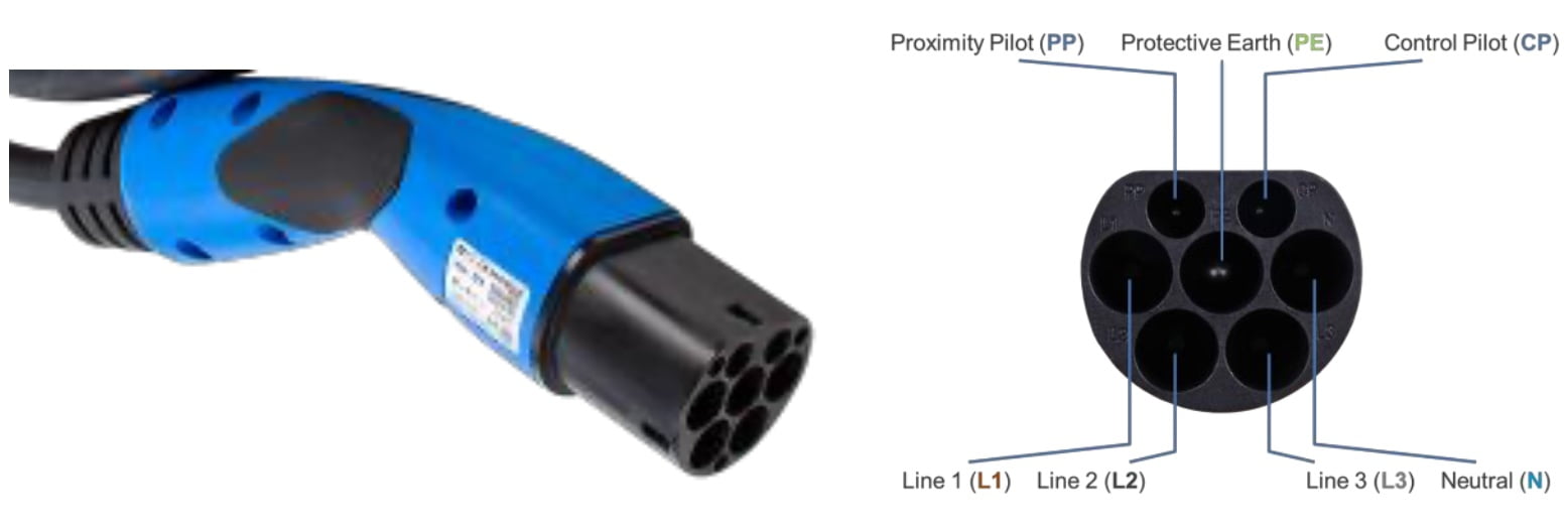
The Protective Earth pin is the same length as the power pins, however, it makes first and breaks last by not having an insulated touch-safe cap. CP and PP pins are shorter than the phase pins and are designed to make last and break first. this gives an added level of protection to the system, as it should make it virtually impossible to remove the cable from a vehicle with the current still flowing.
Control Pilot
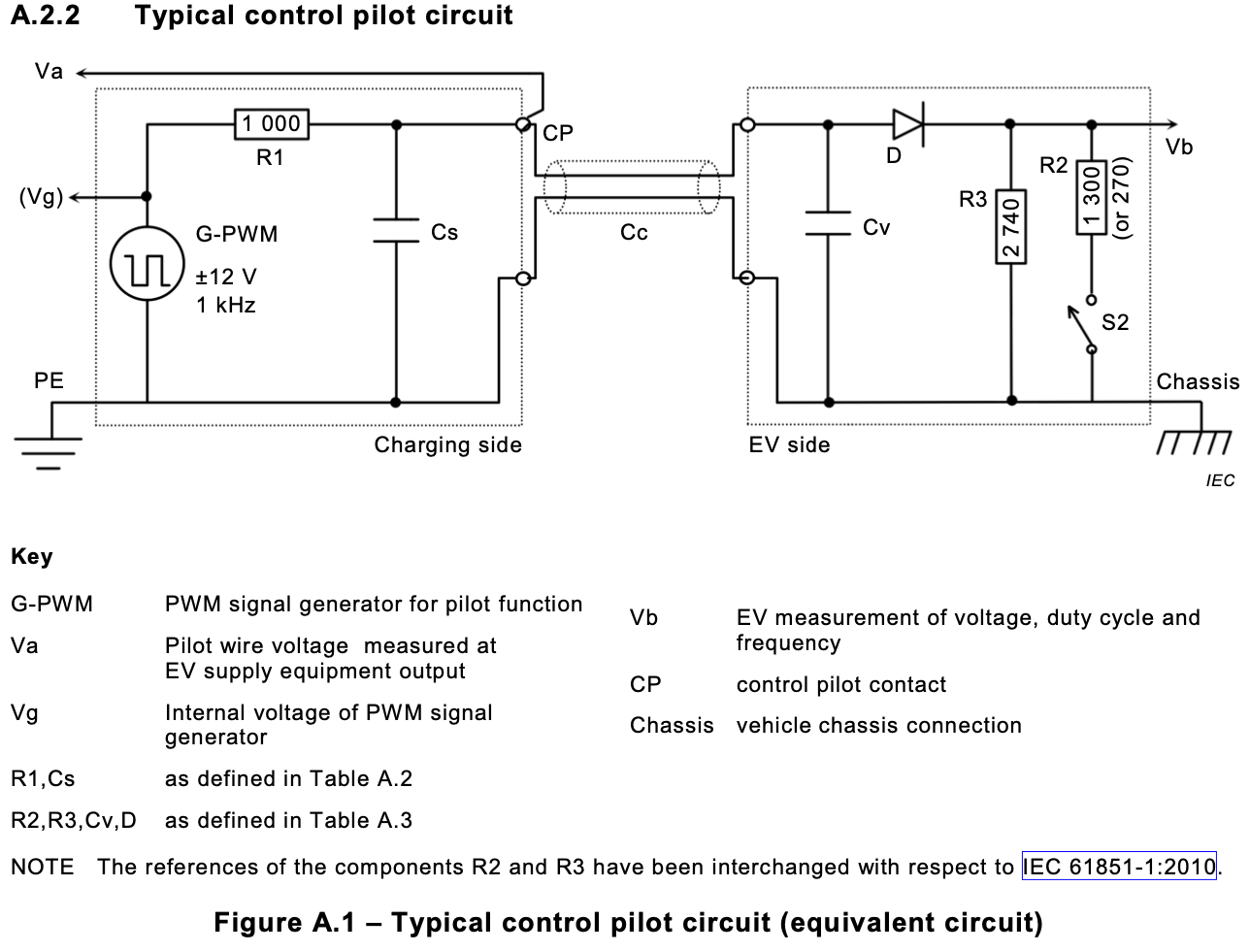
Annex A of BS EN IEC 61851-1 talks about the “Control Pilot function through a control pilot circuit using pulse width modulation (PWM) for Mode 2, Mode 3 and Mode 4”, these are the charging modes described in this post. Mode 4 has some additional requirements, that are described in IEC 61851-23, these will be covered in a subsequent post.
Clause 3.3.3 defines the Control pilot function as a “function used to monitor and control the interaction between the EV and the EV supply equipment”.
There are two levels of control pilot, simplified and typical, either can be used to ensure compliance with SAE J1772 (simplified control pilot is not supported in SAE J1772:2016 and later and should be considered deprecated).
There are several states that can be used to communicate between the EVSE and the EV or PHEV
| State | Definition |
|---|---|
| State A | Either Cable or EV not connected |
| State B | Cable connected to EV and the EVSE |
| State C | EV Charge |
| State D | EV Charge (Ventilation required) |
| State E | Error condition |
| State F | Fault condition |
The operation of these and the values of the PWM and resistor values will be covered in a subsequent post.
Simpified Control Pilot (deprecated)
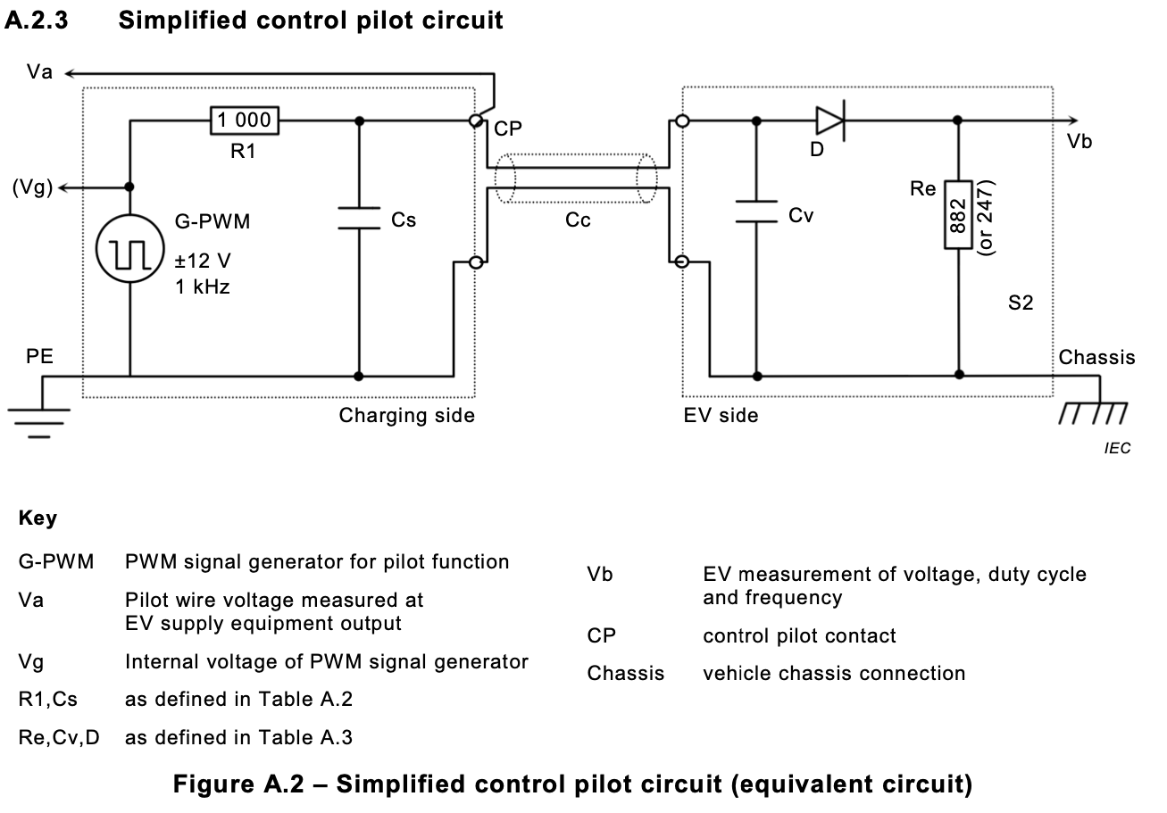
There are several limitations to using the simplified control pilot circuit.
- A simplified control pilot is not supported in SAE J1772:2016 or later and should be considered deprecated.
- An EV using the simplified control pilot circuit shall not draw more than 10 A
- An EV using the simplified circuit shall limit itself to single-phase charging
- There is no provision for creating State B
- If the EVSE detects that the EV is drawing more than the available advertised current (by PWM), then the EVSE may disconnect power.
- The simplified circuit is not recommended for new designs
- The simplified circuit cannot be used in the USA or China.
Typical Control Pilot
Proximity Pilot
Depending on the type of connector, there are two different functions of the proximity contact:
- Type 1 connectors have an auxiliary switch. The charger detects when the electric vehicle is connected and additionally, whether the switch has been latched or not. The EVSE connector is safely attached to the EV only if the auxiliary switch is in the latched position.
- In the case of Type 2 connectors, there is no auxiliary switch. The proximity signal is used for simultaneous proximity detection and current capability coding of the cable assembly. The value of the resistor connected between the proximity contact (PP) and the earthing contact (PE) determines the maximum current capability of the cable assembly (e.g. 13A, 20A, 32A, 63A or 70A). When the charger detects the value of the resistor, it should adjust its maximum current according to the maximum current signalled by the cable resistor. This maximum current value will be then communicated to the electric vehicle via the CP PWM value.
| Current capability of the cable assembly | Value of the resistor PP to PE |
|---|---|
| 13 | 1.5 kΩ |
| 20 | 680 Ω |
| 32 | 220 Ω |
| 63A (3 Phase) / 70 A (single phase) | 100 Ω |


